|
|
||
|---|---|---|
| Documents | ||
| .gitignore | ||
| README.md | ||
| Screen Shot 2018-06-04 at 22.28.05.png | ||
| diff-74b1-b1d3.png | ||
| diff-b1d3-192a.png | ||
| fslrc | ||
| kidiff.sh | ||
| kidiff_gui.py | ||
| plotPCB2.py | ||
| plot_pcbnew.py | ||
| style.css | ||
| tkUI.py | ||
README.md
KiCad-Diff
Was a bash script - new GUI version rewritten in Python3
Scripts for performing image diffs between pcbnew layout revisions. Extended to show the graphical diff in a webpage. Also included some general Kicad/Fossil observations.
Based on the initial scripts of Spuder and described in https://github.com/UltimateHackingKeyboard/electronics/tree/master/scripts
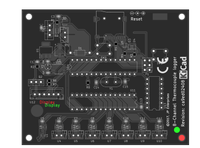
The workflow describes how to use a git repository for Kicad printed circuit board board versions. Kicad uses text files for schematic and pcb layout files. Whilst it is easy enough to generate and diff two pcb layout files, the results are almost meaningless as it is impossible to decide what items have moved where.
Additionally, Spuders workflow relied on git - and I rather prefer Fossil-scm as it is a more complete solution (has a wiki and bugtracker built in) and is a small memory footprint.
https://www.fossil-scm.org/index.html/doc/trunk/www/index.wiki
Also, Spuder's workflow relied on a python script that was downloaded to a /tmp directory. This makes the solution problematic if you are without internet access.
I have added a web interface to this project. It is functional but needs some work to render it more attractive...
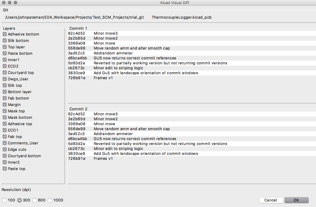
The code is pretty sloppy and fairly sparesly commented but functional. The diff program should be run within a fossil checkout and takes 0, 1 or 2 commit hashes as arguments. With 0 arguments, the script compares the working copy with the last committed version (i.e what has changes since the last commit). With 1 argument, the current checkout is compared to the version identified and with two commit hashes a diff between those versions is calculated.
The diffed versions of the pcb are then used to generate parallel sets of svg files using the kicad python interface. The svg files are then converted to png and cropped to just the board area. Image magick is used to manipulate the images to highlight the changed items. One strategy is to use the stereo 0 command but I had no luck with this and have come up with an alternative method.
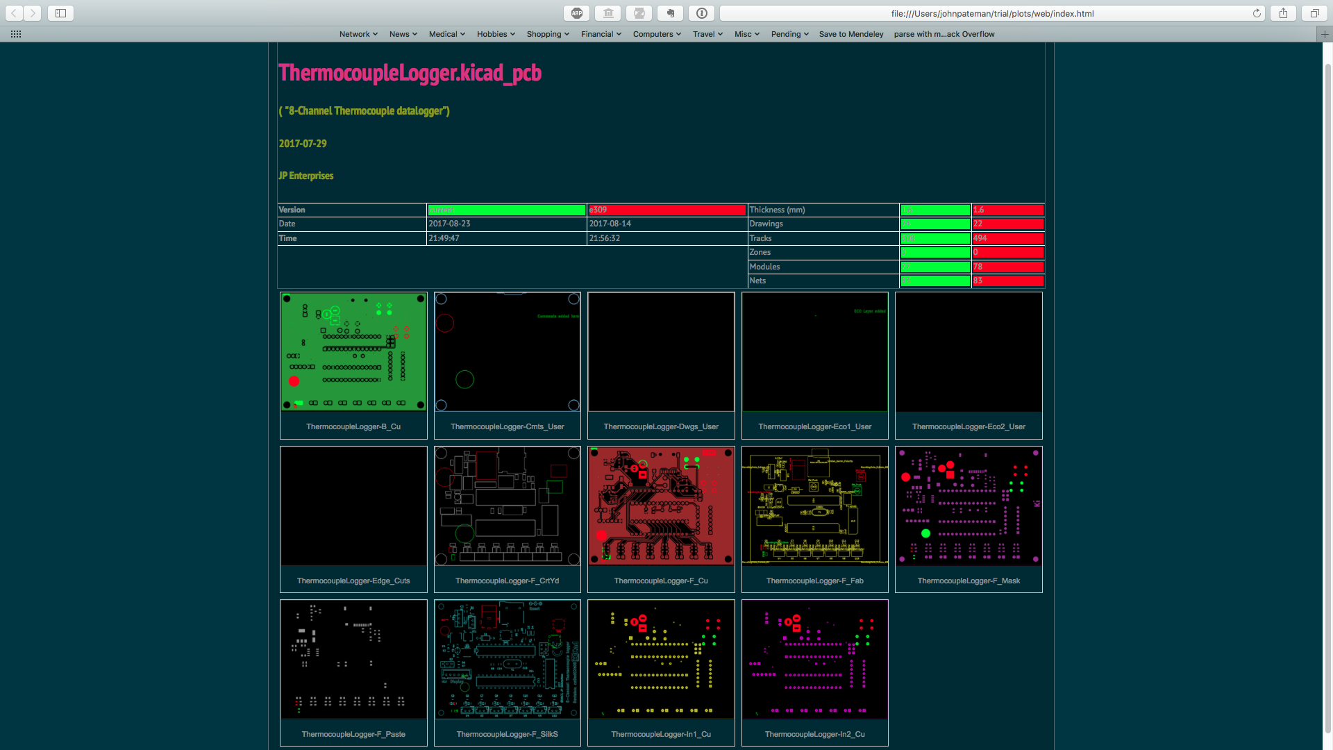
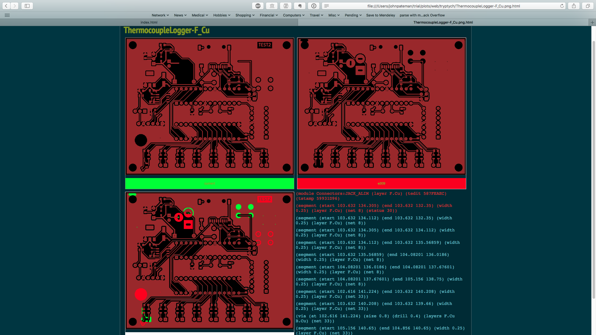
Finally the images are presented in a webpage - clicking an image will bring up a 3-pane diff showing before and after and the composite image with the differences highlighted. The webpage generation code needs abstracting (next part of project). The three pane view is accompanied by a text diff (however, this is very limited and for it to be meaningful really needs a tool to 'reverse parse' the diff and generate a tree structure - i.e a change is noted in a gr-text line but this line is in the s-expression definition of a module that has been moved. Once the diff has been noted, you need to go back up through the s-expression tree to determine the originating module/net etc.
Determining coordinate position is also tricky. It is straightforward to overlay a grid but trickier to compute the necessary offset and scales - this is possible with the python interface but this seems to be in evolution at present. Adjusting or placing an auxillary zero causes problems. Plan to generate a full sized svg image of each page, do the visual diff and then crop the diff to the image extents. Then go back and apply the same crop to the DIFF_1 & DIFF_2 images & at the same time calculate the scale factor and the grid co-ordinates. Working on python parsing of .kicad_pcb file to extract module/track location info. I have doubled the size of the svg to improve the render detailing when converted to png. Would like to be able to do all of thisi in the svg format.
Kicad tends to modify some of the minor data in the checkout making commits a bit 'noisy'. I have adopted the sheme proposed here https://jnavila.github.io/plotkicadsch/ to ammend the kicad files before commiting them. Although there is quite extensive scripting support in fossil it seems quite difficult to replicate the clean and smudge technique reliably in Fossil. There is a wrapper project called fsl (http://fossil.0branch.com/fsl/home) which acts as an interceptor to fossil commands and, additionally offers some extra shortcuts and some more colourful logging options (and the Dresden branch allows the use of simple revision numbers). The behavior is controlled by a ~/.fslrc file which I have included in this repo.
I am running this setup on macOs 10.12 but I would imagine any linux varient would work as well. Windows - ymmv...
Dependencies
- gsed (Mac sed is limited)
- Kicad with python scripting enabled
- Image Magick
- Fossil scm (OR Git or SVN)
- Possibly some others but all have been installed with the help of brew
(If you are on MacOS X and having problems with Imagemagick's convert, you might try reinstalling it with RSVG lib.Using HomeBrew: brew remove imagemagick brew install imagemagick --with-librsvg
Instructions Install plotPCB2.p in /usr/local/bin (or adjust path in lines 480/481 to suit). I could probably add this sort of stuff to a config file but I might wait for V2... Install imagemagick. Run the main script and select a pair of versions in a source controlled repository from the GUI. Select a resolution. The script should build a series of svg files and display the diff in a webpage.
Plans: Rewrite in Python to improve integration with Kicad. DONE Possibly support other VCS tools. DONE Mechanism to select layer sets and resolution. DONE Improvement in parsing and meaning of text diffs. IN PROGRESS
screenshots
GUI
Overview
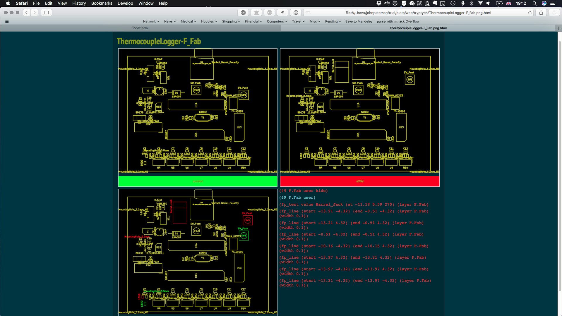
Three panel view
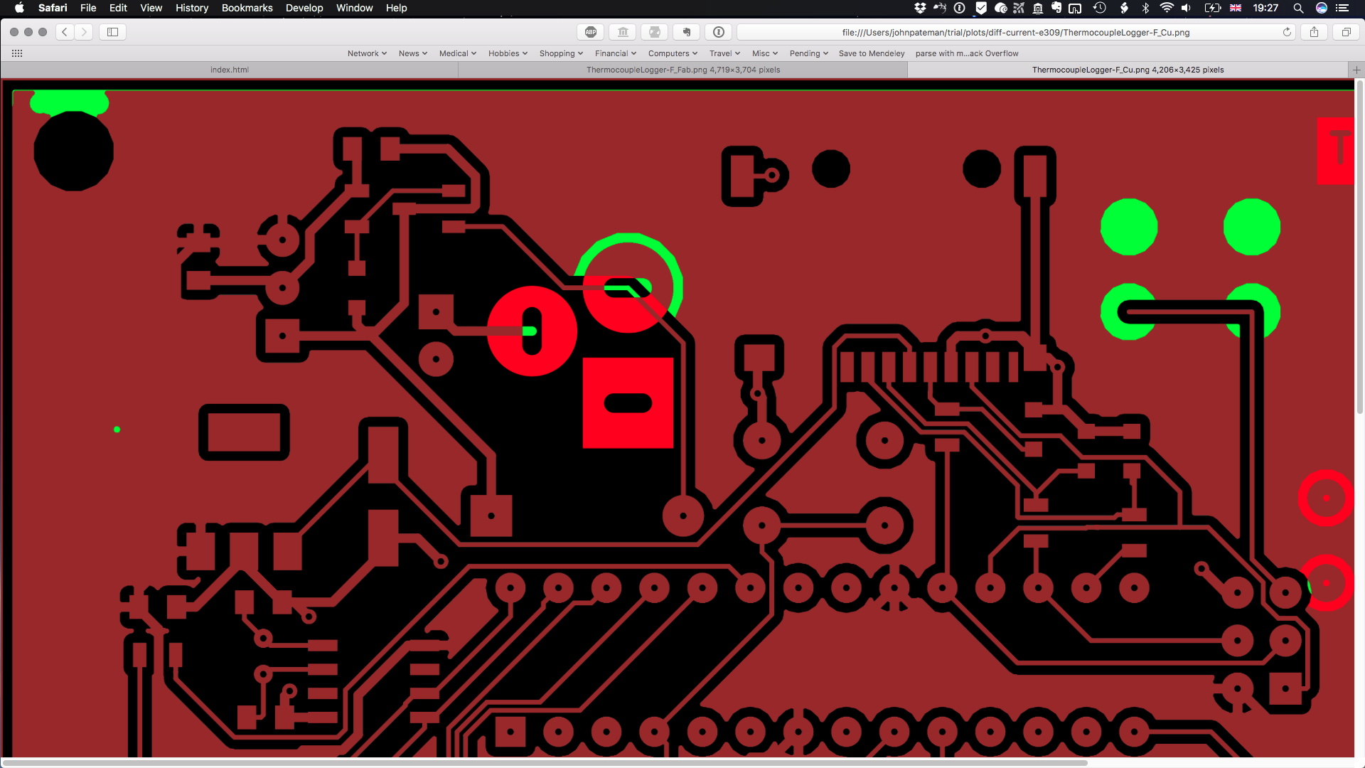
 F_Cu
F_Cu
 F_Cu2
F_Cu2
 F_Fab
F_Fab
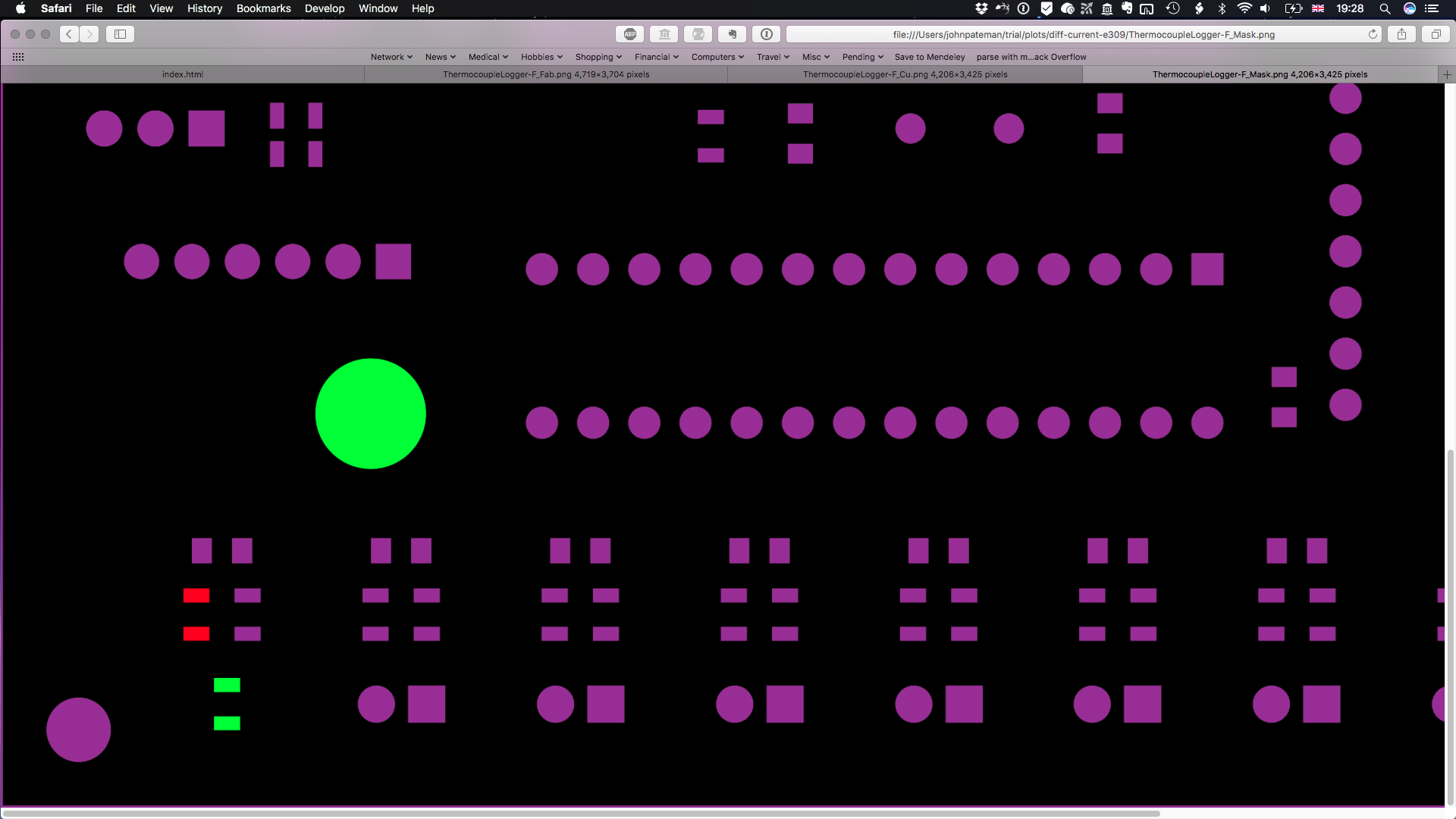
 F_Mask
Output with PCBDraw (In progress)