|
|
||
|---|---|---|
| can_db | ||
| images | ||
| .gitignore | ||
| LICENSE | ||
| README.md | ||
| RaceChronoDiyBleDevice.ino | ||
README.md
RaceChronoDiyBleDevice
DIY BLE device for RaceChrono, currently supports reading data from the CAN bus.
RaceChrono is a lap timer app that supports
collecting all kinds of data: GPS, OBD-II, heart rate, etc.
Most importantly for this project, it allows collecting high quality high
refresh rate data from the CAN bus of a car.
If you're lucky to have a car where the main CAN bus is available on pins 6 and 14 of the OBD-II port (such as 2013-2020 Subary BRZ, Scion FR-S, Toyota 86; NC and ND generation Miatas), you can collect the data from the CAN bus using an affordable OBDLink MX+ reader.
Some newer car cars (2022 Subaru BRZ and Toyota GR86, 2018+ Subaru WRX, many Porsches) isolate the CAN bus from the OBD-II port, so you can only get slow and limited data using the OBD-II protocol. However, if you can find an alternative place to access the CAN bus, you can read data from there -- albeit you'll need to do some custom connections.
This project documents how to make your own DIY device that can listen to the data on the CAN bus of the car, and relay it to RaceChrono using Bluetooth Low Energy (BLE). The code has customizations for my 2022 Toyota GR86, as well as a 2017 Subaru BRZ I used to own, but you should be able to un-do those customizations and do something similar for your car if it's different from those two.
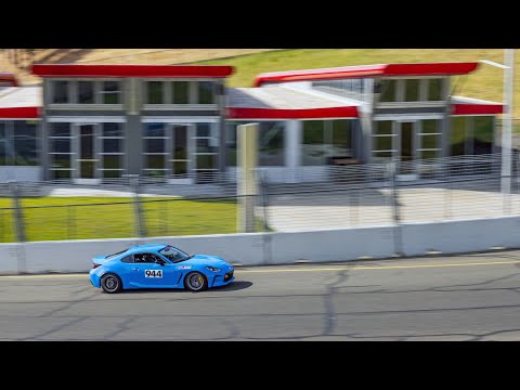
Demo
Here is a video I made in RaceChrono using the data acquired by RaceChrono from a DIY CAN bus reader:
Here is a post with more info on how I got RaceChrono displayed on my headunit via Android Auto.
Safety disclaimer
CAN bus is like a "nervous system" in a car. It is a network that connects various ECUs, sensors, etc. Connecting a new device to this network poses risks such as data corruption, packet losses, etc., that can negatively affect the performance of some or all components of a car. Same applies to incorrect connections and alternations of the CAN bus wiring. This can cause various undesirable effects, such as "Check engine" lights, electrical and mechanical damage, loss of control, injuries and even death.
By using any information or code in this project you assume any and all risk, and release any liability from the author(s) and contributors to this project.
Assembling the hardware
This section describes how to build the hardware for the CAN bus reader with a JST SM connector. The connector can then be used to connect to a car-specific harness for the CAN bus.
Recommended parts list:
- Adafruit ItsyBitsy nRF52840 Express
- MCP2515 boards (2+ pcs recommended so you can test without a car)
- 16 MHz quarz oscillators (in case your MCPs have 8 MHz quartzes)
- Jumper (in case your MCP comes without it, like mine)
- Mini Breadboard
- Jumper wires
- JST SM connectors
- Crimping tool for JST connectors
- ~22 AWG wires
First, solder the male headers to your microcontroller board. You'll need G, 3V, SCK, MO, MI and 7. It's also recommended to solder 9, R and USB for future improvements and mechanical stability on the breadboard. Soldering male headers is a lot easier if you first insert them into a breadboard.
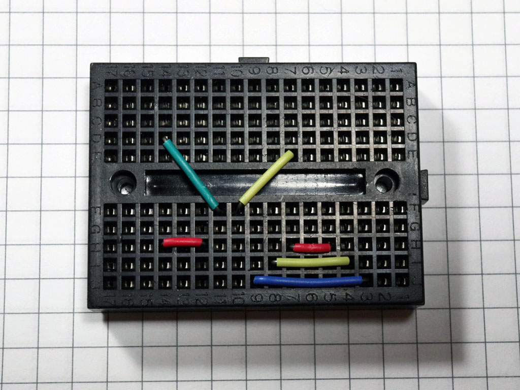
Put the jumpers on the breadboard this way to allow for neat hidden connections:
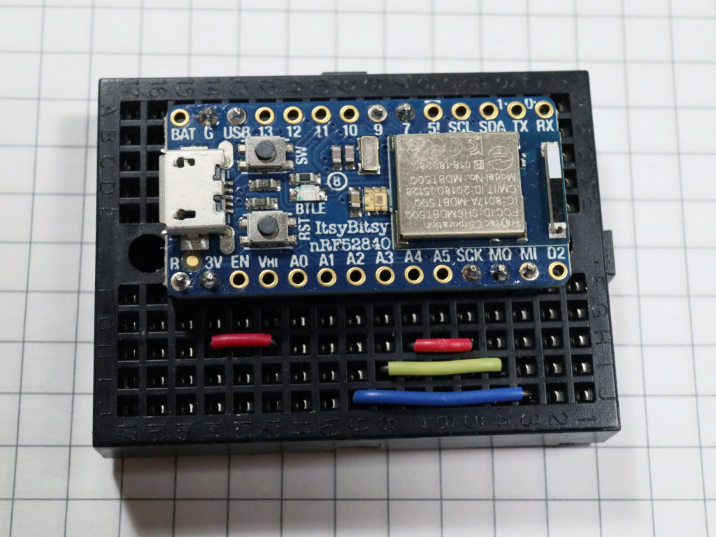
Then, put the microcontroller board on the breadboard:
Un-solder the header from the MCP board and solder a new header on the other side of the board to make it more breadboard-friendly.
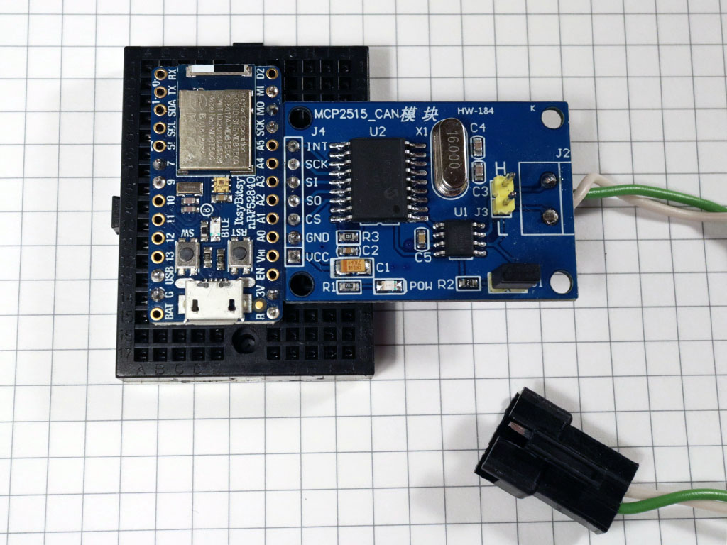
Replace the 8 MHz quartzes on your MCPs with 16 MHz quartzes, if needed. Optionally, un-solder the screw terminal and solder a twisted pair of wires to the board, and finish with a nice JST SM connector:
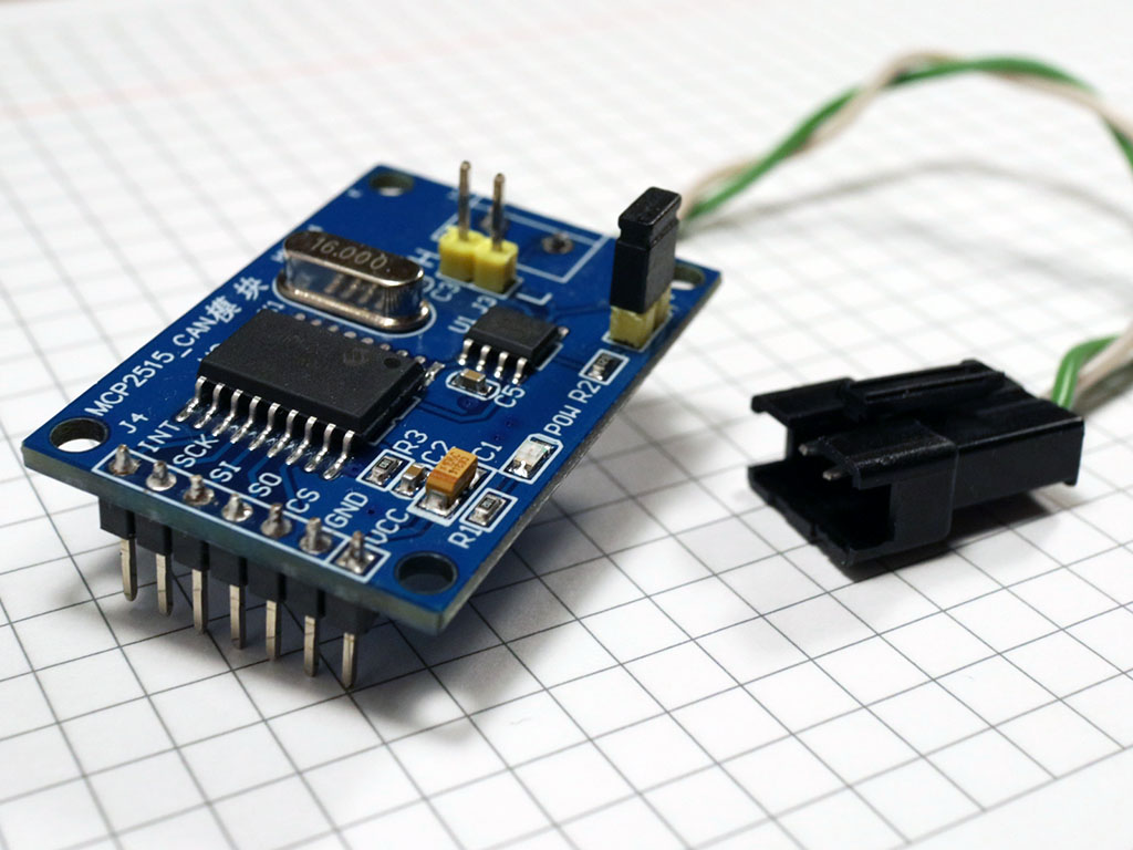
I suggest using a white cable for CAN L and a colored cable for CAN H. If you use a consistent color scheme for these wires and for the harness you use in your car, it will be easier to make sure you get the polarity right.
Finally, put the MCP on the breadboard.
Check connections:
| MCP pin | Microcontroller pin |
|---|---|
| VCC | 3V |
| GND | G |
| CS | 7 |
| SO | MI |
| SI | MO |
| SCK | SCK |
| INT | Currently unused, may use 9 in the future |
Optionally, put everything into a nice enclosure, but make sure to keep the twisted pair with the JST connector available, as well as the USB port for power and programming.
Installing the firmware
You will need to install two Arduino libraries before you can build the project:
cd ~/Documents/Arduino/libraries/  # ~/Arduino/libraries on Mac OS
git clone https://github.com/timurrrr/arduino-CAN CAN
git clone https://github.com/timurrrr/arduino-RaceChrono arduino-RaceChrono
It's important that you don't use the arduino-CAN library available in the Arduino IDE built-in library manager, as it has multiple bugs, and many operations are implemented in an ineffective way. My pull requests to address those have not been reviewed at the time of writing.
Once everything is set up, compile and upload the RaceChronoDiyBleDevice.ino
"sketch" using Arduino IDE.
Tweaking to work with your car
This particular project was designed for FT86 cars (Subaru BRZ, Toyota 86/GT86/GR86, Scion FR-S). You can search for "BRZ" in the source code to see where the customizations were made, and tweak to work better with your car.
If you do have an FT86 car, you might want to read
on how to make a harness between the CAN bus and the reader, as well as how to set up data channels in RaceChrono.
Some information about the CAN data has been documented for Mazda MX-5/Miata (NC generation and ND generation).
If you know CAN IDs and equations for other track cars, feel free to send a pull request!
It might be nice to make these customizations programmable via a mobile app and store the preferences in the flash storage of the nRF52840, but currently this has not been implemented to keep the code minimalistic and easier to read.
Testing
You don't need to always be in the car to test changes.
Instead, you can build another device (possibly using a cheaper board, such as
Arduino Uno), and use the
FakeSubaruBRZ example
from my fork of the arduino-CAN library, and connect the two boards into a
small CAN network. Note that you don't need to use a jumper to connect the
120 Ohm resistor on the second board in a CAN network (right?).
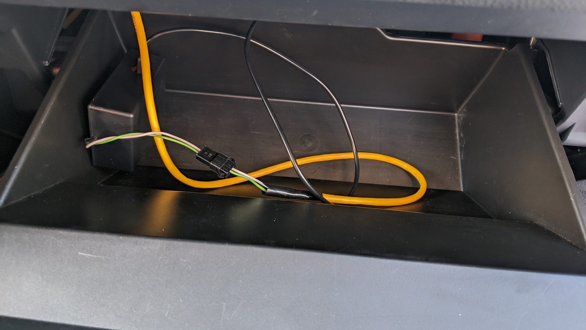
When you're sure that you've assembled everything correctly and basic tests pass on your table top with a "fake car" device, it's time to put things into the car. Here's how the final setup looked like in my 2017 Subaru BRZ:
If you have reliability issues with the CAN bus, try installing a jumper to connect the 120 Ohm terminal resistor in parallel to the CAN chip.
Contributions
I'd be happy to add more info on the CAN protocol for other popular sport cars. Feel free to send pull requests!
Support the project
I hope you found this project useful, entertaining, educating, etc. Personally, I was amazed that for just ~$50 it's possible to get a data logging system comparable to the "go to" devices that HPDE enthusasts use that cost 10x+ more. And since the "brain" of such a data acquisition system is RaceChrono, you don't need to fiddle with cables, laptops, etc. to review your data when you come back to the pits between sessions.
Having said that, I've spent a few too many evenings on this project, and this is not my paid job. I have some more exciting ideas on how to further improve this project, make it more accessible, support more car models... but can't justify spending too much more time on it. If you want to thank me for what I've already shared, or support my future ideas, I will appreciate it if you send me some "boba tea money".
Here's a PayPal shortcut for your convenience:
