|
|
||
|---|---|---|
| .. | ||
| README.md | ||
| backend.tf.sample | ||
| diagram-network.png | ||
| diagram.png | ||
| main.tf | ||
| outputs.tf | ||
| variables.tf | ||
| versions.tf | ||
README.md
Hub and Spoke via VPC Peering
This example creates a simple Hub and Spoke setup, where the VPC network connects satellite locations (spokes) through a single intermediary location (hub) via VPC Peering.
The example shows some of the limitations that need to be taken into account when using VPC Peering, mostly due to the lack of transivity between peerings:
- no mesh networking between the spokes
- complex support for managed services hosted in tenant VPCs connected via peering (Cloud SQL, GKE, etc.)
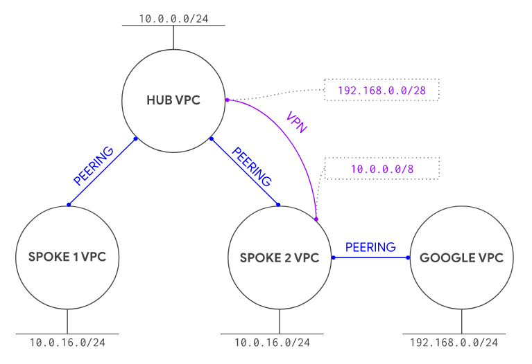
One possible solution to the managed service limitation above is presented here, using a static VPN to establish connectivity to the GKE masters in the tenant project (courtesy of @drebes). Other solutions typically involve the use of proxies, as described in this GKE article.
One other topic that needs to be considered when using peering is the limit of 25 peerings in each peering group, which constrains the scalability of design like the one presented here.
The example has been purposefully kept simple to show how to use and wire the VPC modules together, and so that it can be used as a basis for more complex scenarios. This is the high level diagram:
Managed resources and services
This sample creates several distinct groups of resources:
- one VPC each for hub and each spoke
- one set of firewall rules for each VPC
- one Cloud NAT configuration for each spoke
- one test instance for each spoke
- one GKE cluster with a single nodepool in spoke 2
- one service account for the GCE instances
- one service account for the GKE nodes
- one static VPN gateway in hub and spoke 2 with a single tunnel each
Testing GKE access from spoke 1
As mentioned above, a VPN tunnel is used as a workaround to avoid the peering transitivity issue that would prevent any VPC other than spoke 2 to connect to the GKE master. This diagram illustrates the solution
To test cluster access, first log on to the spoke 2 instance and confirm cluster and IAM roles are set up correctly:
gcloud container clusters get-credentials cluster-1 --zone europe-west1-b
kubectl get all
The next step is to edit the peering towards the GKE master tenant VPC, and enable export routes. You can do it directly in Terraform with the GKE module `peering_config' variable, via gcloud, or on the cloud ccnsole. We're leaving it as an option, since one of the goals of this example is to allow testing both working and non-working configurations.
Export routes via Terraform
Change the GKE cluster module and add a new variable after private_cluster_config:
  peering_config = {
    export_routes = true
    import_routes = false
  }
If you added the variable after applying, simply apply Terraform again.
Export routes via gcloud
The peering has a name like gke-xxxxxxxxxxxxxxxxxxxx-xxxx-xxxx-peer, you can edit it in the Cloud Console from the VPC network peering page or using gcloud:
gcloud compute networks peerings list
# find the gke-xxxxxxxxxxxxxxxxxxxx-xxxx-xxxx-peer in the spoke-2 network
gcloud compute networks peerings update [peering name from above] \
  --network spoke-2 --export-custom-routes
Then connect via SSH to the spoke 1 instance and run the same commands you ran on the spoke 2 instance above, you should be able to run kubectl commands against the cluster. To test the default situation with no supporting VPN, just comment out the two VPN modules in main.tf and run terraform apply to bring down the VPN gateways and tunnels. GKE should only become accessible from spoke 2.
Operational considerations
A single pre-existing project is used in this example to keep variables and complexity to a minimum, in a real world scenario each spoke would use a separate project (and Shared VPC).
A few APIs need to be enabled in the project, if apply fails due to a service not being enabled just click on the link in the error message to enable it for the project, then resume apply.
The VPN used to connect the GKE masters VPC does not account for HA, upgrading to use HA VPN is reasonably simple by using the relevant module.
Variables
| name | description | type | required | default |
|---|---|---|---|---|
| project_id | Project id for all resources. | string |
✓ | |
| ip_ranges | IP CIDR ranges. | map(string) |
... |
|
| ip_secondary_ranges | Secondary IP CIDR ranges. | map(string) |
... |
|
| private_service_ranges | Private service IP CIDR ranges. | map(string) |
... |
|
| region | VPC region. | string |
europe-west1 |
Outputs
| name | description | sensitive |
|---|---|---|
| vms | GCE VMs. |

