Also add .gitignore for Mac OS |
||
|---|---|---|
| can_db | ||
| images | ||
| .gitignore | ||
| LICENSE | ||
| README.md | ||
| RaceChronoDiyBleDevice.ino | ||
README.md
RaceChronoDiyBleDevice
DIY BLE device for RaceChrono, currently supports reading data from the CAN bus.
There are some optimizations in the code that are specific to the FT86 platform cars (Subaru BRZ, Toyota 86, Scion FR-S), but it should be straightforward to tweak the code for other cars.
Supported Hardware
- Adafruit Feather nRF52832
- Adafruit ItsyBitsy nRF52840 Express
- 16 MHz MCP2515 breakout boards (probably MCP25625 as well)
Prerequisites
You will need to install two libraries for Arduino:
cd ~/Documents/Arduino/libraries/  # ~/Arduino/libraries on Mac OS
git clone https://github.com/timurrrr/arduino-CAN CAN
git clone https://github.com/timurrrr/arduino-RaceChrono arduino-RaceChrono
It's important that you don't use the arduino-CAN library available in the Arduino IDE built-in library manager, as it has multiple bugs, and many operations are implemented in an ineffective way. My pull requests to address those have not been reviewed at the time of writing.
Assembling
Recommended parts list:
- Adafruit ItsyBitsy nRF52840 Express
- MCP2515 boards (2+ pcs recommended so you can test without a car)
- 16 MHz quarz oscillators (in case your MCPs have 8 MHz quartzes)
- Jumper (in case your MCP comes without it, like mine)
- Mini Breadboard
- Jumper wires
- JST SM connectors
- Crimping tool for JST connectors
- ~22 AWG wires
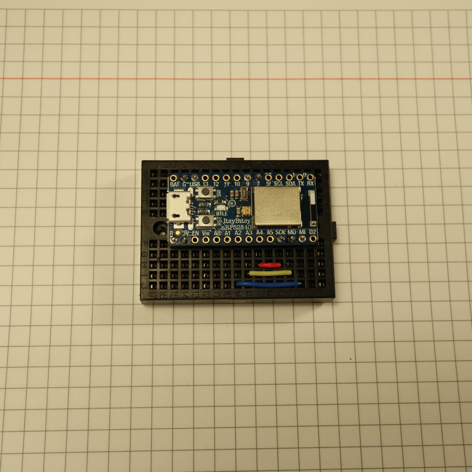
First, solder the male headers to your microcontroller board. You'll need G, USB, SCK, MO, MI and 7. It's also recommended to solder 9, R and 3V for future improvements and mechanical stability on the breadboard. Soldering male headers is a lot easier if you first insert them into a breadboard.
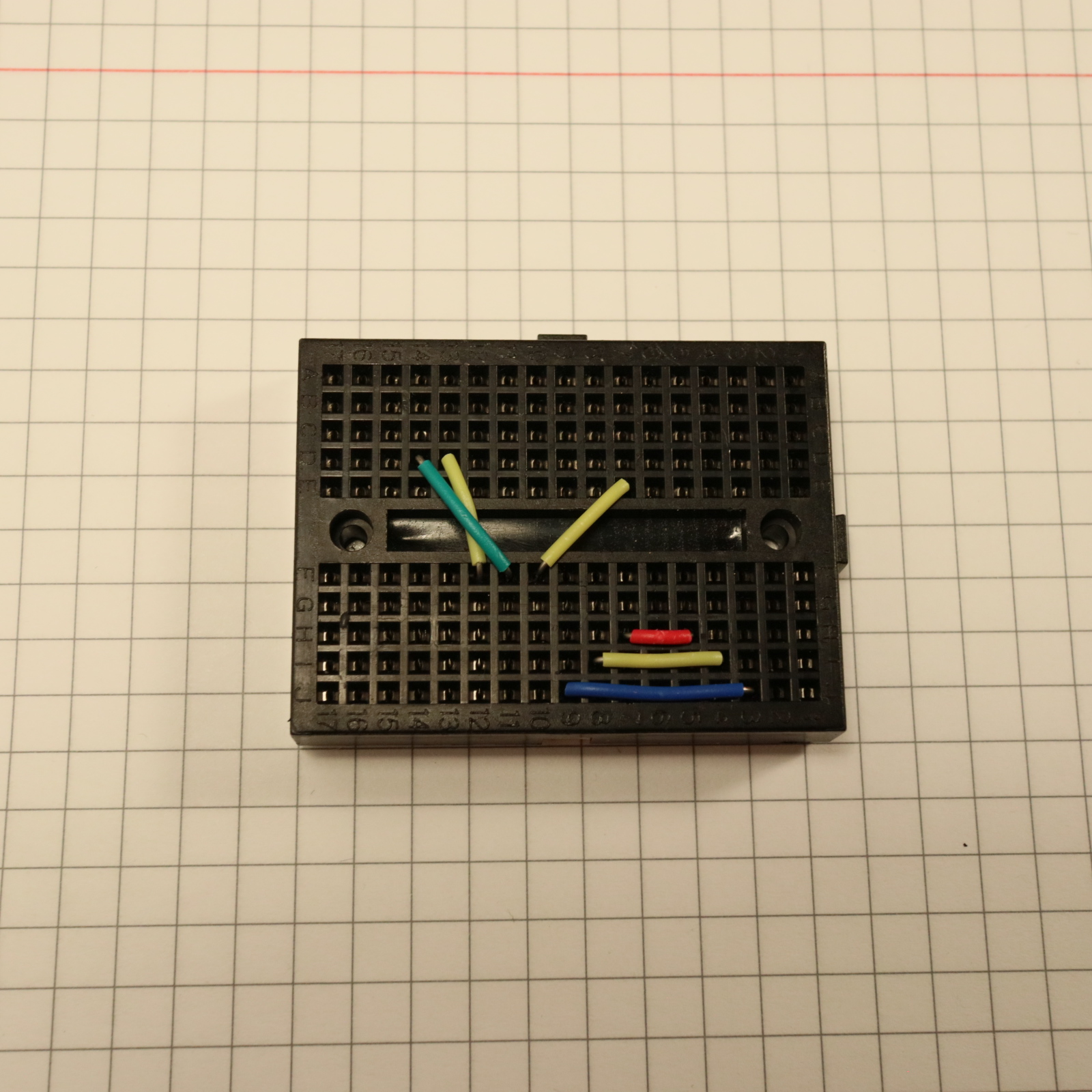
Put the jumpers on the breadboard this way to allow for neat hidden connections:
Then, put the microcontroller board on the breadboard:
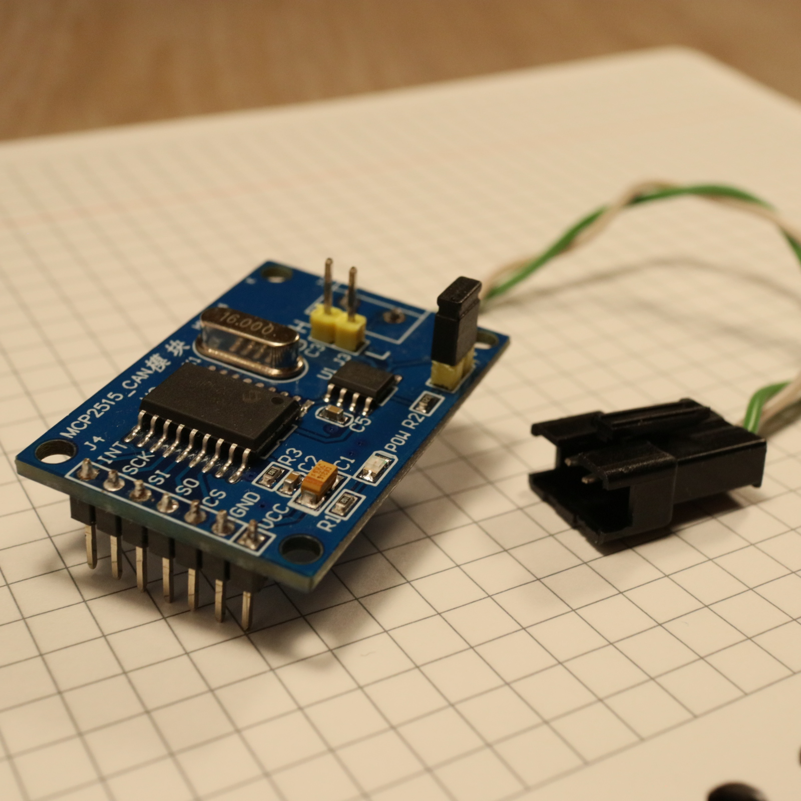
Un-solder the header from the MCP board and solder a new header on the other side of the board to make it more breadboard-friendly.
Replace the 8 MHz quartzes on your MCPs with 16 MHz quartzes, if needed. Install the jumper that connects the 120 Ohm terminal resistor. Optionally, un-solder the screw terminal and solder a twisted pair of wires to the board, and finish with a nice JST SM connector:
Finally, put the MCP on the breadboard.
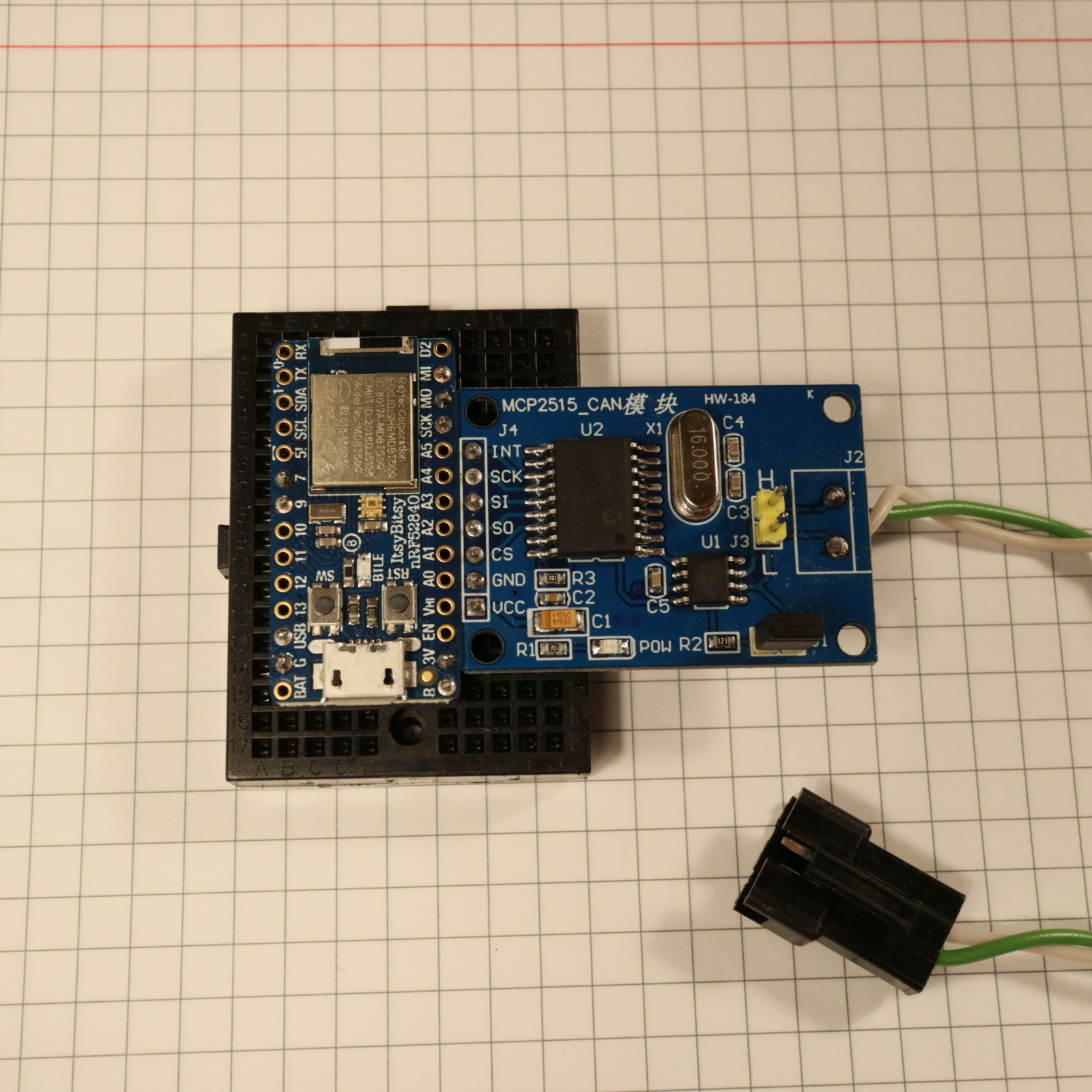
Check connections:
| MCP pin | Microcontroller pin |
|---|---|
| VCC | USB |
| GND | G |
| CS | 7 |
| SO | MI |
| SI | MO |
| SCK | SCK |
| INT | Currently unused, may use 9 in the future |
Optionally, put everything into a nice enclosure.
Tweaking to work with your car
This particular example is optimized to work with FT86 cars (Subaru BRZ, Toyota 86, Scion FR-S). You can search for "BRZ" in the source code to see where the customizations were made, and tweak to work better with your car.
If you do have an FT86 car, you might want to read the info on messages that these cars are known to send over their CAN network.
It might be nice to make these customizations programmable via a mobile app and store the preferences in the flash storage of the nRF52840, but currently this has not been implemented to keep the code minimalistic and easier to read.
Testing
You don't need to always be in the car to test changes.
Instead, you can build another device (possibly using a cheaper board, such as
Arduino Uno), and use the
FakeSubaruBRZ example
from my fork of the arduino-CAN library, and connect the two boards into a
small CAN network. Note that you don't need to use a jumper to connect the
120 Ohm resistor on the second board in a CAN network (right?).