6.5 KiB
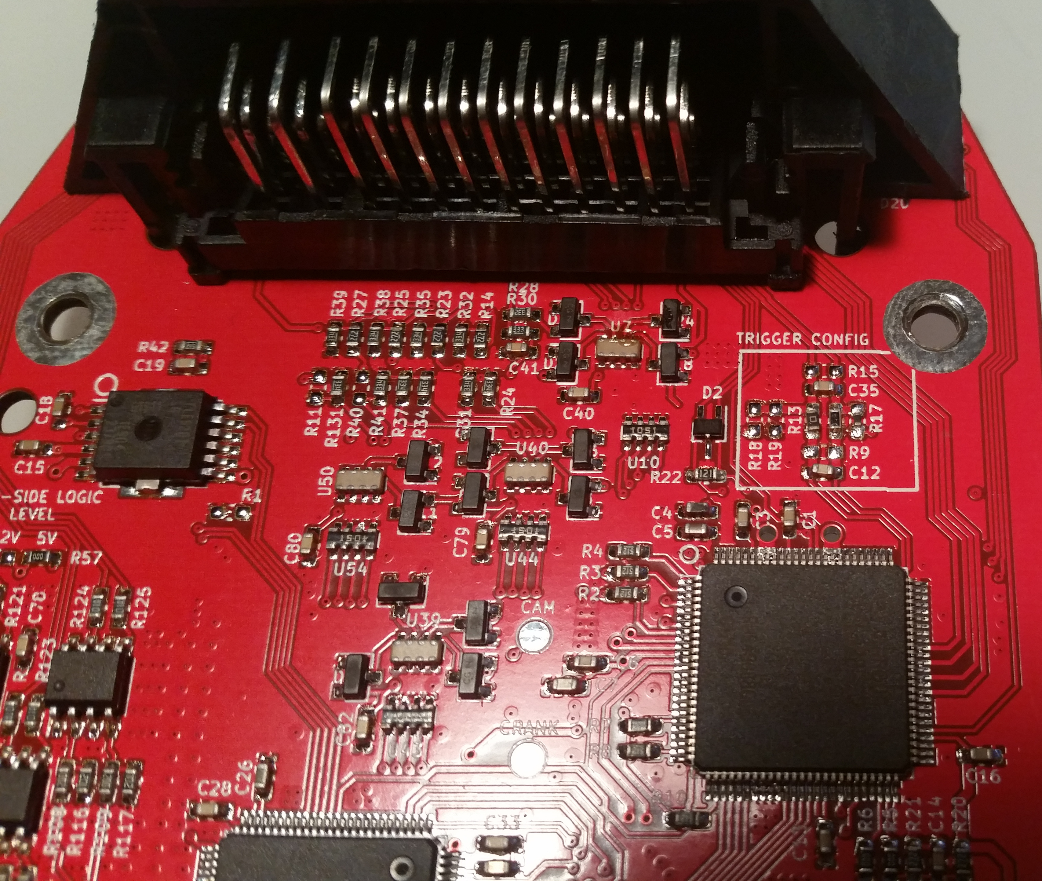
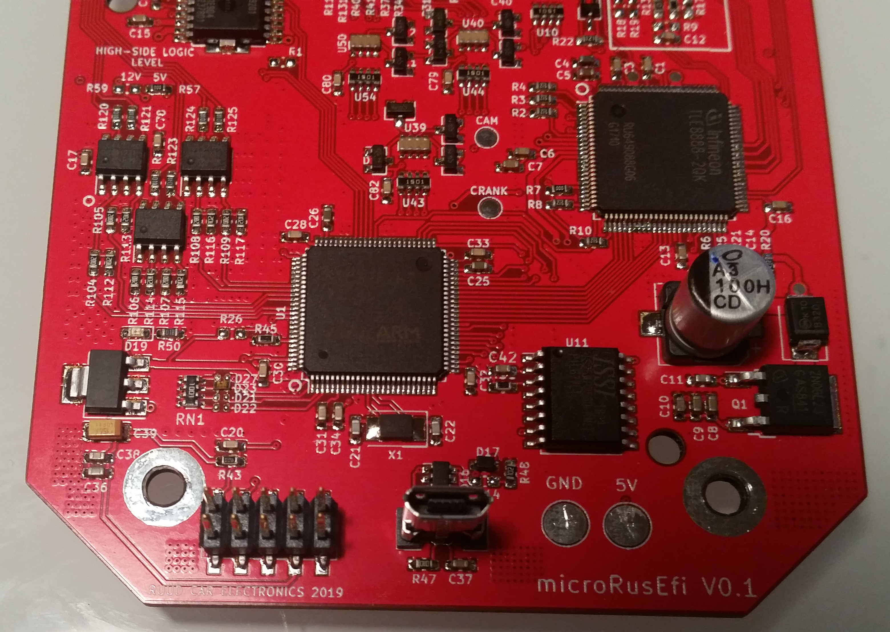
microRusEFI Wiring
Connector Pinout
WARNING: for historical reasons microRusEFI pin numbers do not match Molex numbers on the plastic
In some cases without "main relay output +12v" both pins #1 and #5 should be connected to the single source of +12v.
Pin #1 feeds ETB H-bridge, battery voltage sense, gp5 & gp6 high-side +12v, TLE8888 H-bridges.
Pin Types
These tables provide technical information about the different types of pin found on microRusEFI.
Power
| Pin | ID | Type | Notes & Limits |
|---|---|---|---|
| . | 12V | Power supply | 9-22V operating, 5A fuse recommended |
| #2, #6 | pgnd | Power ground | Solidly ground directly to chassis or engine block. |
| #17, #21 | sgnd | Signal ground | Sensor ground. Do not ground to engine! |
| . | 5v | 5V sensor supply | 5V supply for external sensors. 200mA maximum per pin. |
Stepper
| Pin | Name | Notes & Limits |
|---|---|---|
| #33 | GP3 | Stepper Coil #2 |
| #34 | GP2 | Stepper Coil #1 |
| #35 | GP1 | Stepper Coil #1 |
| #43 | GP4 | Stepper Coil #2 |
Input
| ID | Type | Notes & Limits | Possible functions |
|---|---|---|---|
| at | Analog temperature | Analog temperature (thermistor) input. 2.7k(+-1%) pullup resistor to 5v | Thermistor temperature sensor, fuel level sender (variable resistor type) |
| av | Analog voltage | Analog voltage input. 500k pull down to GND | Analog voltage sensor (MAP, TPS, acc pedal, oil pressure, etc) |
| vr | Variable reluctance | VR crank input | VR sensors including crank, cam, vehicle speed |
| hall | Hall cam/crank | TBD pull up to 5v hall sensor for cam/crank | Hall sensors including crank, cam, vehicle speed |
Output
| ID | Type | Notes & Limits | Possible functions |
|---|---|---|---|
| inj | Injector output | Low side, 2.2A maximum Only saturated (high impedance) injectors are supported. | Injector, general purpose low side |
| ign | Ignition output | 5V push-pull, 250mA maximum | Ignition coil, general purpose 5V push-pull |
| ls | High power low side | General purpose low side output, 4.5A maximum | General purpose low side, injector |
| gp_high | General purpose high side | General purpose high side push output, 5V/12V (internally selectable based on JP2 jumper) 250mA maximum | General purpose 5V/12V high side, ignition coil |
| gp_low | General purpose low side | General purpose low side pull output, 12V 500mA maximum | General purpose low side |
| gp_pp | General purpose Push-Pull | General purpose push-pull (low and high side) output, 600mA | Bipolar IDLE stepper, relays, solenoids |
| mr | Main relay | Dedicated main relay output. Low side turned on with power, 800mA maximum. | Main relay |
| etb | Electronic throttle | Dedicated electronic throttle outputs. Connect a brushed motor throttle body directly to these two pins. |
Communication
| ID | Type | Notes & Limits |
|---|---|---|
| usb | USB | USB tuning interface |
| can | CAN bus | CAN communication |
USB cable green wire: USB D+ DATA+
USB cable white wire: USB D- DATA-
USB cable black wire: ground
USB cable red wire: +5v (would not work via microRusEFI connector for versions < 0.5.0)
Hall type Crank sensor
See TLE8888 data sheet figure 71 R9=DNP R15=DNP R17=2.7K pull-up to 5v
R12=10K R13=0R
Extra pins
microRusEFI exposes the following pins in addition to the primary 48 pin connector:
J4:
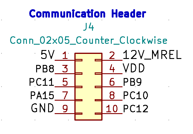
| N | Name | Possible functions (not all listed!) |
|---|---|---|
| 9 | GNS | GND |
| 4 | VDD | 3.3V |
| 1 | 5V | 5V |
| 2 | 12V | 12V from Main Relay |
| 3 | PB8 | I2C1_SCL or CAN1_RX |
| 6 | PB9 | I2C1_SDA or CAN1_TX |
| 8 | PC10 | SPI3_SCK or USART3_TX or UART4_TX |
| 5 | PC11 | SPI3_MISO or USART3_RX or UART4_RX |
| 10 | PC12 | SPI3_MOSI or USART3_CK or UART5_TX |
| 7 | PA15 | SPI3_NSS (Chip Select) |
Three GPIOs are available on J2 (SWD) connector. If you are not going to use debugger J2 connector can be used for other purposes.
| N | Name | Possible functions (not all listed!) |
|---|---|---|
| 7, 8 | GND | GND |
| 1, 2 | 5V | 5V |
| 3, 4 | VDD | 3.3V |
| 5 | SCK | SWD clock or PA14 gpio (no alternative functions) |
| 9 | SWDIO | SWD data or PA13 gpio (no alternative functions) |
| 6 | SWO | SWD/JTAG data out (?) or SPI1_SCK or SPI3_SCK |
| 10 | NRST | CPU reset input (active low) |
For HW version 0.5.0 and newer some additional GPIOs are available on test points around STM32.
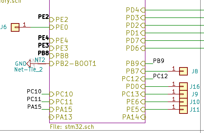
| Test point | GPIO | Possible functions (not all listed!) |
|---|---|---|
| J6 | PE0 | GPIO |
| J8 | PB7 | USART1_RX or TIM4_CH2 |
| J9 | PC13 | GPIO only |
| J10 | PE6 | TIM9_CH2 |
| J11 | PE5 | TIM9_CH1 |
| J16 | PD0 | CAN1_RX |
Please refer to STM32F407 chip documentation for full list of alternative functions of GPIOs listed above.
FAQ
Q: Can I use temperature inputs for EGT?
A: "temperature input" is a just an analog 0-5v input with a strong pull-up implied to use with a thermistor. Your EGT sensor is probably not a thermistor, your 0-5v output out of a conditioner would probably not be happy about the pull-up.