2.8 KiB
Vault Of Mercedes-Benz OEM Information
Diagnostic Manuals, for all Engines (Volume 1 to 3) see http://manual.startekinfo.com/manual/JSP/engines.jsp
M111 - I4
99 SLK230 See Mercedes-C230-and-SLK230
Jimmy, Scott have M111 2.3 Compressor engine, both as swaps into 190e body wireing detailes
Alex has M111 1.8 (now swaped M111.961) Forum
M112 v6 320
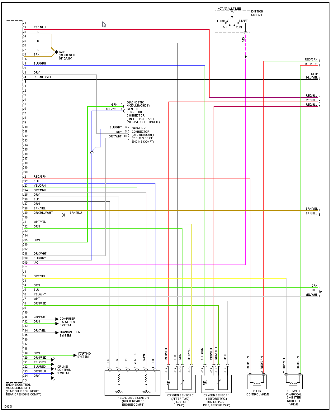
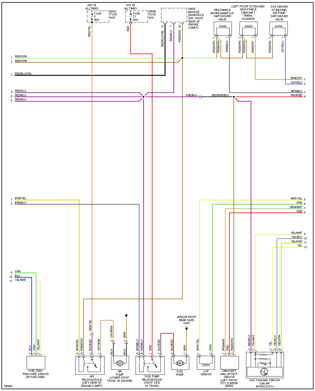
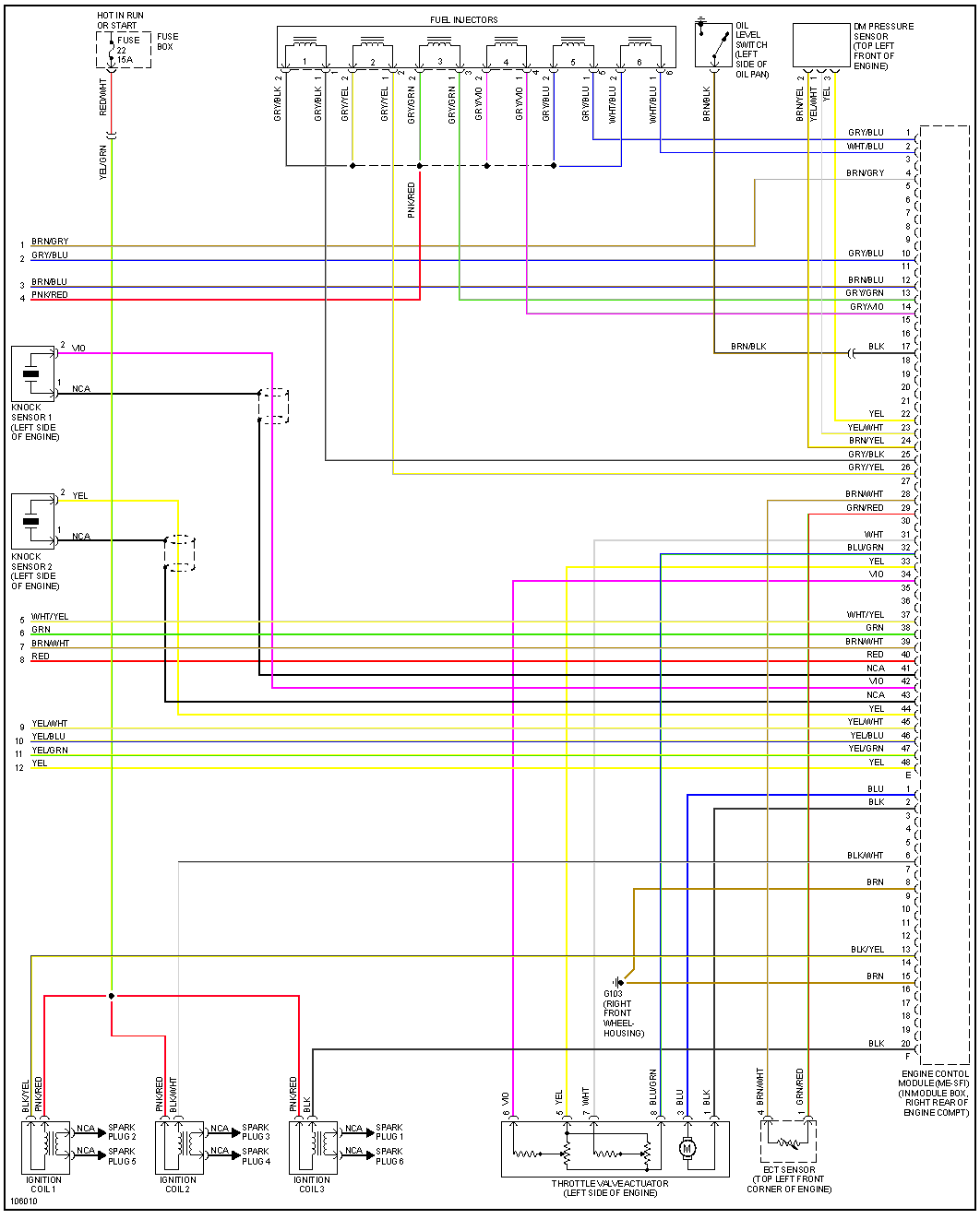
1999-e320 Connector and Wiring
M113 v8
430
1999-e430 Connector and Wiring
2000-s430 Connector and Wiring
M113K is 113.990 or 113.991? Looks like 134 pin connector?
M156 looks like 154 pin connector? WebETM Starfinder is amazing?
2011 W212 E63 1569001300 ME9.7
1997 S320
Mercedes OEM Engine harness layout (ME2.0/1/8)
This is helpful information for swapping or building your own "improved" Engine Harness. ME2.0/1, (Roughly MY96/7 to MY99), the stock ECM for a Hellen128 system will have 2 plugs for E/F in the ECM, and then a handful of other plugs depending on chassis. W210 chassis will have 210 545 81 28 (Black Strip Plug), R129 will have 029 545 72 28 (Green Oval Plug), W202/208/170 may have both. In addition to the Engine Harness, most cars with ME2.0/1/8 ECMs also have rear mounted batteries, there will be a bulkhead connector on the firewall which connects to the starter; these cars will also have 722.6 Transmissions, which have a 13 pin connector on the right side of the transmission.
The strip or oval plugs connect a handful of accessory sensors, power leads, and the starter wire. In General, on a MB wiring harness, plain brown is GND, plain red is +V, purple is starter circuit.
Seen here is a 029 545 72 28 from a MY97 R129 SL320. Purple wire on pin 13 is starter signal Blue/Yellow wire on pin 12 is A/C Compressor Blue/Green wire on pin 9 is a sensor on the Oil Filter housing Brn/Wht wire on pin 7 is GND Brn/Wht wire on pin 6 is ECM GND Black/Green wire on pin 3 is IGN +V Red/Green wire on pin 2 is VVT/Resonance Flap +V Red/Blue wire on pin 1 is INJ +V
NB These plugs are not indicated on the wiring diagrams posted here.


