2.8 KiB
2.8 KiB
TREZOR Core Hardware
TREZOR v2 Open Source Hardware Reference Documentation
Photo Front
TODO
Photo Back
TODO
Bill of Materials / BOM
TODO
Eagle Schematic
TODO
Eagle Board
TODO
Developer Kit
- 1 x STM32F429I-DISC1
- 1 x USB Cable Type A Plug/Male to Type Mini-B Plug/Male
- 1 x USB Cable Type A Plug/Male to Type Micro-B Plug/Male
- 1 x ER-TFTM028-4 Display + Capacitive Touch Panel Module (Note: specify 40-Pin Header, 8080 8-bit Parallel, VDD=3.3V, Capacitive Touch Panel)
- 1 x microSD Board
- 28 x Female to female jumper wires with 0.1" header contacts
Display
- Resolution: 240px x 240px -OR- 240px x 320px
- Driver IC: ST7789V or ILI9341V (on-chip display data RAM of 240x320x18 bits)
- 18-bit (262,144) RGB color graphic type TFT-LCD
- Bus/Interface: 8080-I 8-bit parallel with 16-bit/pixel (RGB 5-6-5)
Pinout
| Description | MCU Pin | Notes |
|---|---|---|
| LCD_RST | PC14 | display module pin 21 |
| LCD_FMARK | PD12 | tearing effect input; display module pin 22 |
| LCD_PWM | PA7 | backlight control (brightness); display module pin 29 |
| LCD_CS | PD7 | display module pin 23 |
| LCD_RS | PD11 | register select aka command/data; display module pin 24 |
| LCD_RD | PD4 | display module pin 26 |
| LCD_WR | PD5 | display module pin 25 |
| LCD_D0 | PD14 | display module pin 3 |
| LCD_D1 | PD15 | display module pin 4 |
| LCD_D2 | PD0 | display module pin 5 |
| LCD_D3 | PD1 | display module pin 6 |
| LCD_D4 | PE7 | display module pin 7 |
| LCD_D5 | PE8 | display module pin 8 |
| LCD_D6 | PE9 | display module pin 9 |
| LCD_D7 | PE10 | display module pin 10 |
Capacitive Touch Panel / Sensor
- Bus/Interface: I2C
- Driver IC: FT6236 or FT6206
- single touch
Pinout
| Description | MCU Pin | Notes |
|---|---|---|
| I2C1_SCL | PB6 | display module pin 30 |
| I2C1_SDA | PB7 | display module pin 31 |
| EINT | PC4 | display module pin 39 |
| REST | PC5 |
microSD Socket
- Bus/Interface: 4-bit
Pinout
| Description | MCU Pin |
|---|---|
| SDIO_D0 | PC8 |
| SDIO_D1 | PC9 |
| SDIO_D2 | PC10 |
| SDIO_D3 | PC11 |
| SDIO_CK | PC12 |
| SDIO_CMD | PD2 |
| SD_CARDDETECT | PC13 |
USB Socket
- USB HS (high-speed) peripheral in FS (full-speed) mode
Pinout
| Description | MCU Pin |
|---|---|
| OTG_HS_VBUS | PB13 |
| OTG_HS_ID | PB12 |
| OTG_HS_DM | PB14 |
| OTG_HS_DP | PB15 |
Dev Board
- STM32F429ZIT6
- HSE / High-Speed External Crystal: 8 MHz
- Integrated STMicroelectronics ST-LINK/V2.1 debugger
Minimum MCU requirements:
- STM32F4 family STM32F427VIT6
- 168 MHz, 8 MHz HSE
- 2048 KB Flash memory
- 192 KB SRAM
- 64 KB CCMRAM
- FMC controller
- TRNG
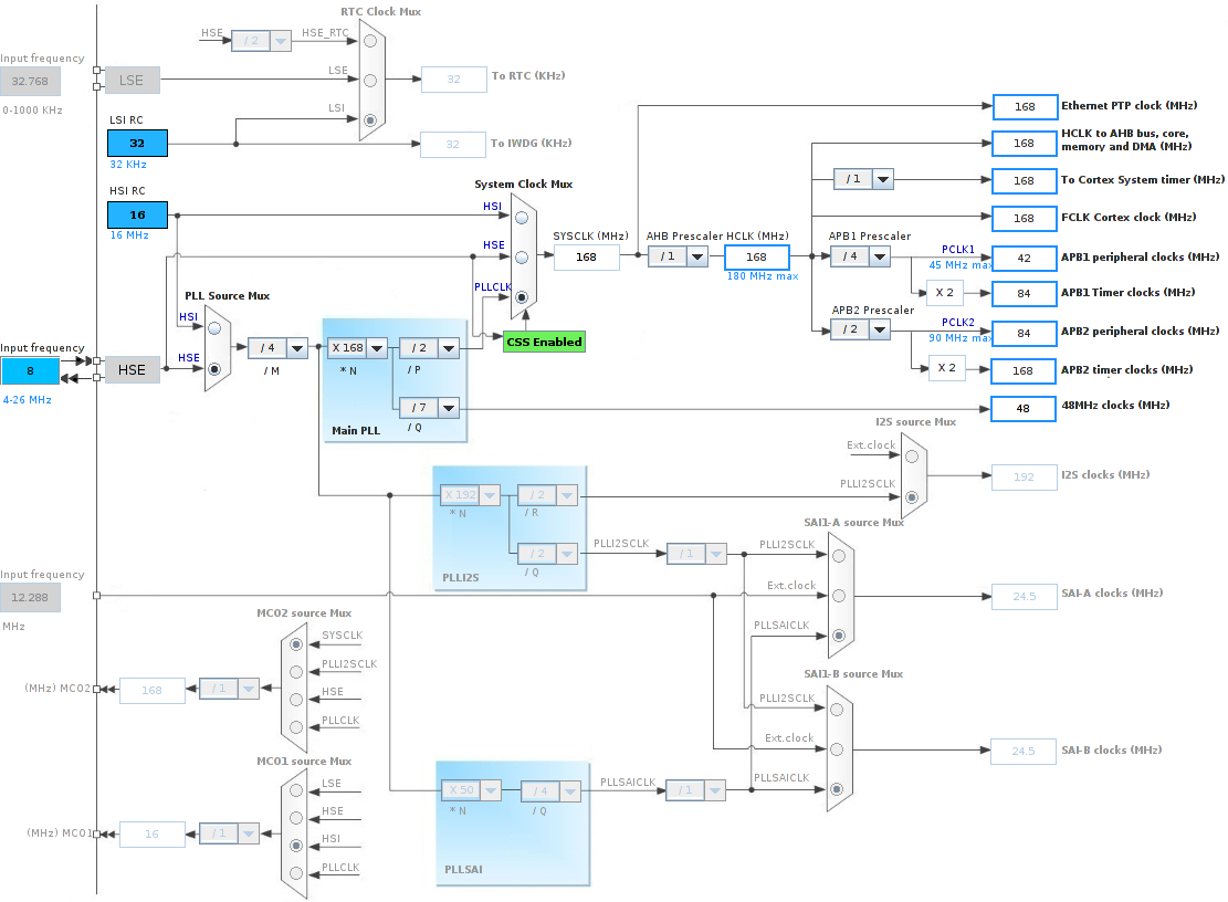
Clock Tree