|
|
||
|---|---|---|
| .github | ||
| Firmware | ||
| Hardware | ||
| Pictures | ||
| .gitignore | ||
| README.md | ||
README.md
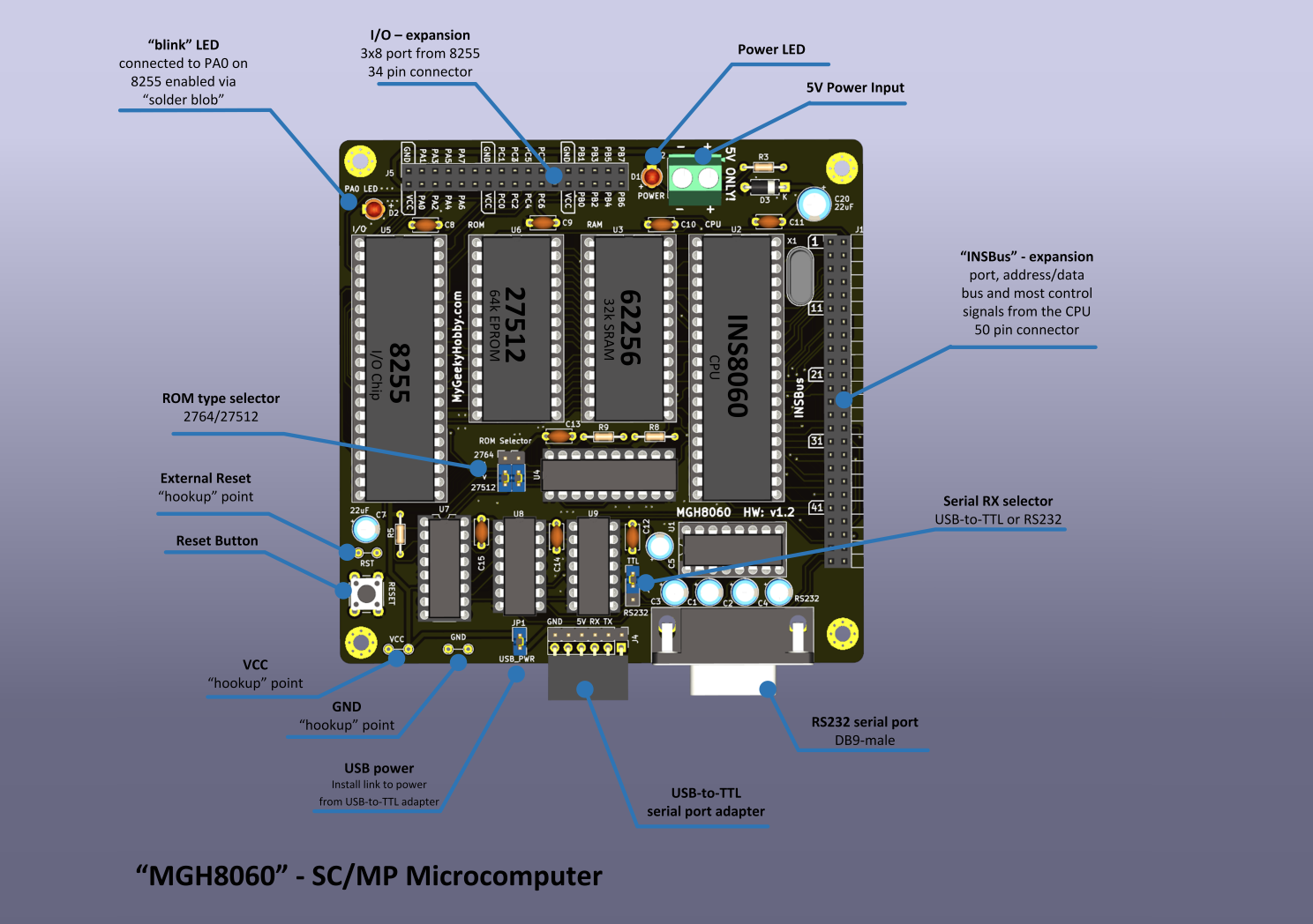
MGH8060
SC/MP INS8060-based microcomputer running National Industrial Basic Language (NIBL)
Here is an overview of the device:
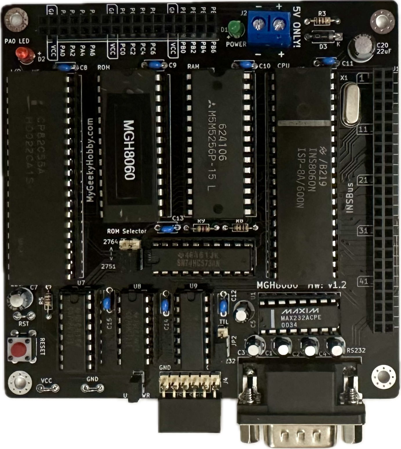
And here is my assembled unit - hardware v1.2
Bill of Materials
| Component type | Reference | Description | Quantity |
|---|---|---|---|
| PCB | Order from PCBWay | 1 | |
| Integrated Circuit | U1 | MAX232(A) - RS232 Driver, 16 pin DIP | 1 |
| Integrated Circuit | U2 | INS8060 - SC/MP II Microcontroller, 40 pin DIP | 1 |
| Integrated Circuit | U3 | HM62256B - 32kb SRAM, 28 pin DIP | 1 |
| Integrated Circuit | U4 | 74LS573 - high-speed octal latch, 20 pin DIP | 1 |
| Integrated Circuit | U5 | 8255A - Programmable Peripheral Interface, 40 pin DIP | 1 |
| Integrated Circuit | U6 | 27C512 - 64kb EPROM, 28 pin DIP | 1 |
| Integrated Circuit | U7 | 74LS138 - 3-to-8 line decoder, 16 pin DIP | 1 |
| Integrated Circuit | U8 | 74LS21 - Dual 4 -Input AND Logic, 14 pin DIP | 1 |
| Integrated Circuit | U8 | 74LS04 - HEX Inverter, 14 pin DIP | 1 |
| LED | D1 | LED indicator, 3 mm | 1 |
| LED | D2 | LED indicator, 3 mm | 1 |
| Diode | D3 | 1N4002, general-purpose diode | 1 |
| Pin Header | J1 | 2x17 header female, 2.54 mm pitch | 1 |
| Connector | J2 | Screw terminal | 1 |
| Connector | J3 | DB9 male | 1 |
| Pin Header | J4 | 1x6 pin header, 2.54 mm pitch, angle | 1 |
| Pin Header | J5 | 2x25 header female, 2.54 mm pitch | 1 |
| Pin Header | J6 | 1x6 pin header, 2.54 mm pitch | 1 |
| Pin Header | JP1 | 1x2 pin header, 2.54 mm pitch | 1 |
| Pin Header | JP2-JP4 | 1x3 pin header, 2.54 mm pitch | 3 |
| Capacitor | C8-C15 | 1 uF, 16V, electrolytic, 2.54 mm pitch | 5 |
| Capacitor | C6 | 27pF, ceramic, 2.54 mm pitch | 1 |
| Capacitor | C8-C15 | 0.1 uF, 50V, MLCC, 5 mm pitch | 8 |
| Capacitor | C7,C20 | 22uF, 6.8V, electrolytic, 2.54 mm pitch | 2 |
| Resistor | R1 | 160 kohm, 0.125 W, axial | 1 |
| Resistor | R2-R4,R8 | 1 kohm, 0.125 W, axial | 4 |
| Resistor | R5 | 10k kohm, 0.125 W, axial | 1 |
| Resistor | R9 | 4.7k kohm, 0.125 W, axial | 1 |
| Crystal | X1 | 4MHz, short 3.5mm heigh max | 1 |
| IC Socket | U8,U9 | 14 pin DIP | 2 |
| IC Socket | U1,U7 | 16 pin DIP | 2 |
| IC Socket | U4 | 20 pin DIP | 1 |
| IC Socket | U3,U6 | 28 pin DIP | 2 |
| IC Socket | U2,U5 | 40 pin DIP | 2 |
Memory Map
| Start | End | RAM | ROM | I/O |
|---|---|---|---|---|
| 0x0000 | 0x1FFF | X | ||
| 0x2000 | 0x3FFF | X | ||
| 0x4000 | 0x5FFF | X | ||
| 0x6000 | 0x7FFF | X | ||
| 0x8000 | 0x9FFF | X | ||
| 0xA000 | 0xBFFF | X | ||
| 0xC000 | 0xDFFF | X | ||
| 0xE000 | 0xFFFF | X |
| Address | 8255 Function |
|---|---|
| 0xA000 | Port A |
| 0xA001 | Port B |
| 0xA002 | Port C |
| 0xA003 | Ctrl Register |
Schematic
Credits
-
The device is based on the work of Ronald Dekker
-
Early versions of my design were reviewed by Phil(aka Retro Phil) who offered a lot of helpful suggestions, he also contributed all the firmware for MGH8060
Release Notes
I used HCT parts for most of the ICs. Power usage was about 60mA
I used Winbond W27C512 (EEPROM pin compatible with EPROMs)
Please consider getting the PCB from my sponsor PCBWay

If you found this helpful and you like the work I do, why not buy me a coffee, thanks! :)

Changes
-
Version 1.2:
- Fixed missing connections.
-
Version 1.1:
- Corrected CE signals (thanks Phil)
-
Version 1.0
- Initial version
License
Copyright 2024 Kris Sekula
This work is licensed under a Creative Commons Attribution-NonCommercial 4.0 International (CC BY-NC 4.0) .
Trademarks
- Other names and brands may be claimed as the property of others.