8.0 KiB
8.0 KiB
See also HOWTO-Crimp-Ampseal
See also Vault-Of-Electronic-Throttle-Bodies-ETB Nissan Hitachi SERA576-01 60mm throttle body recommended.
~6 wires are different between Proteus 0.2 and Proteus 0.3 - all on the 23 pin plug.
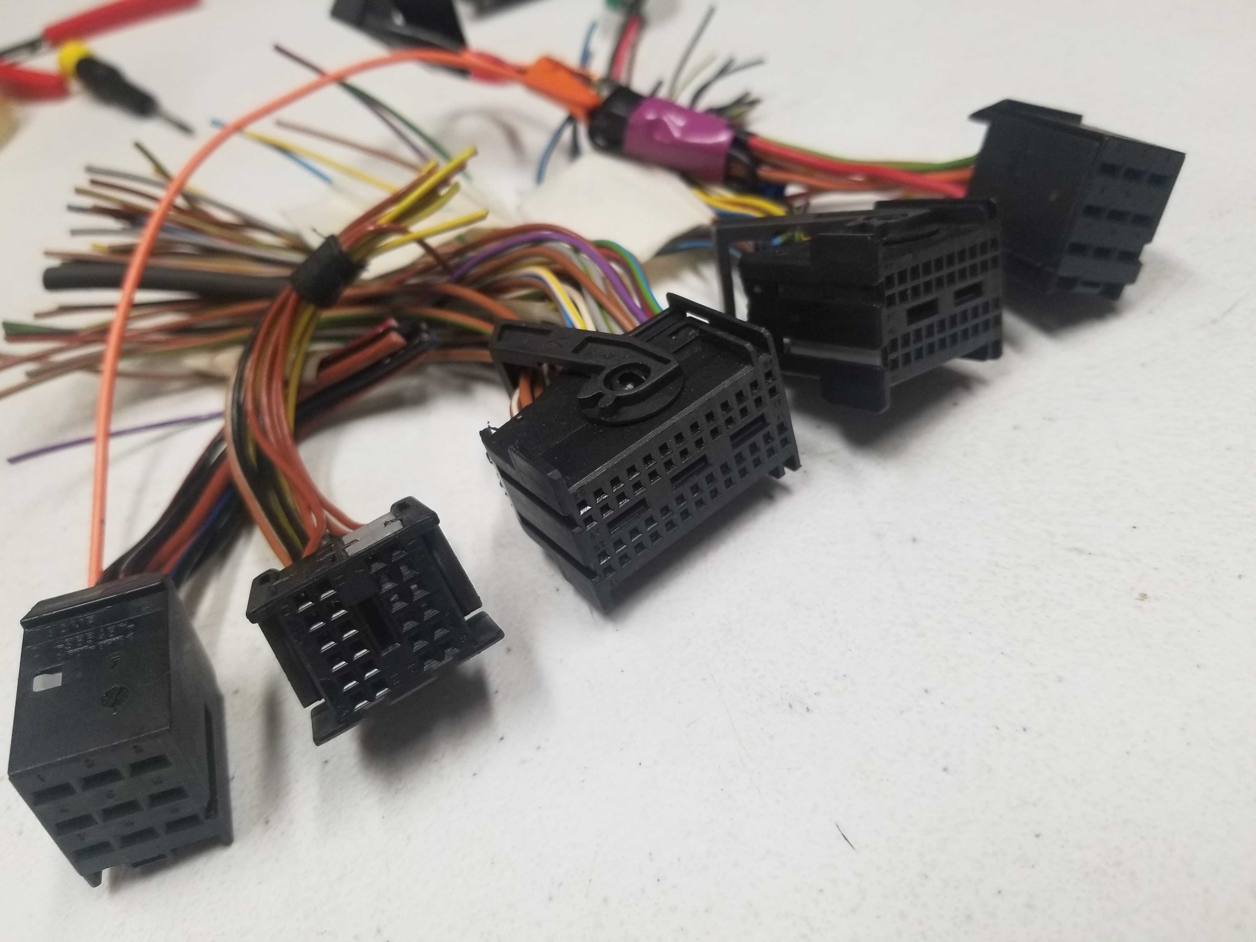
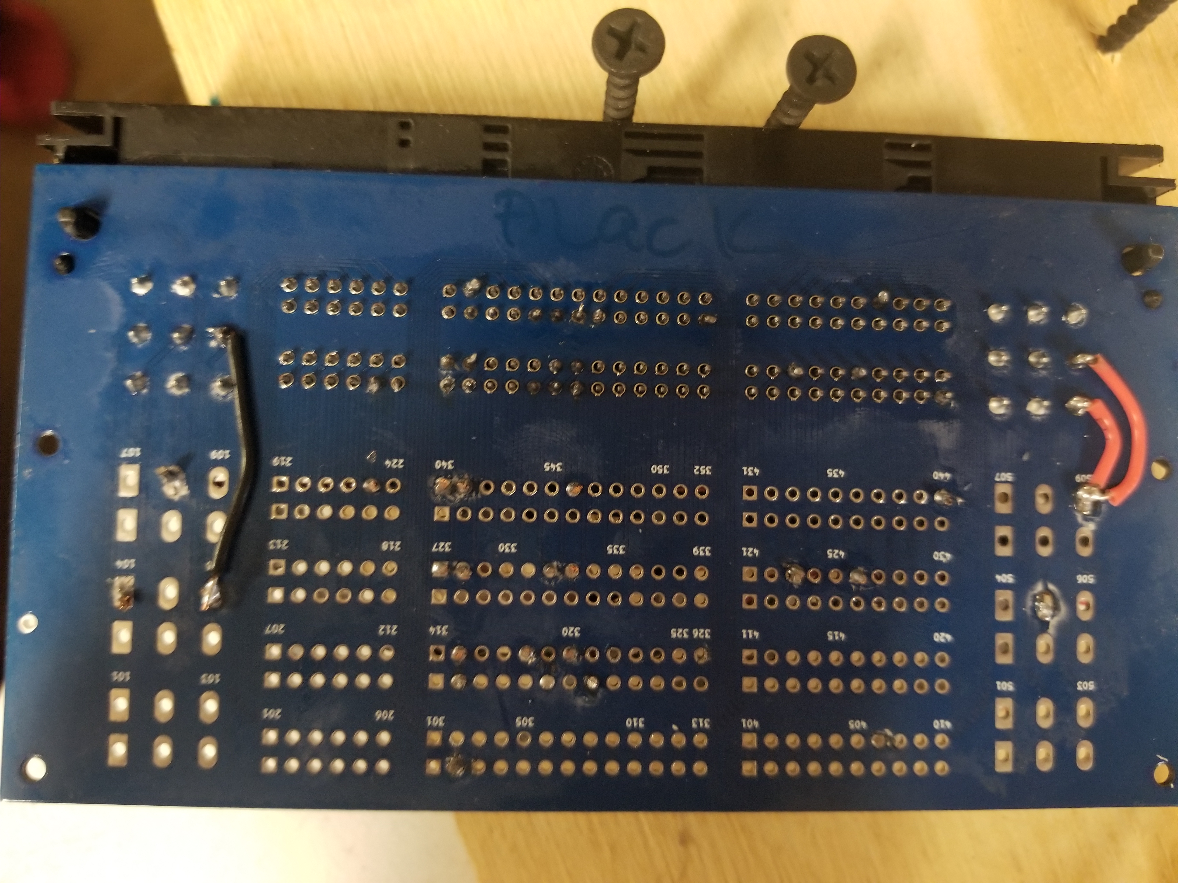
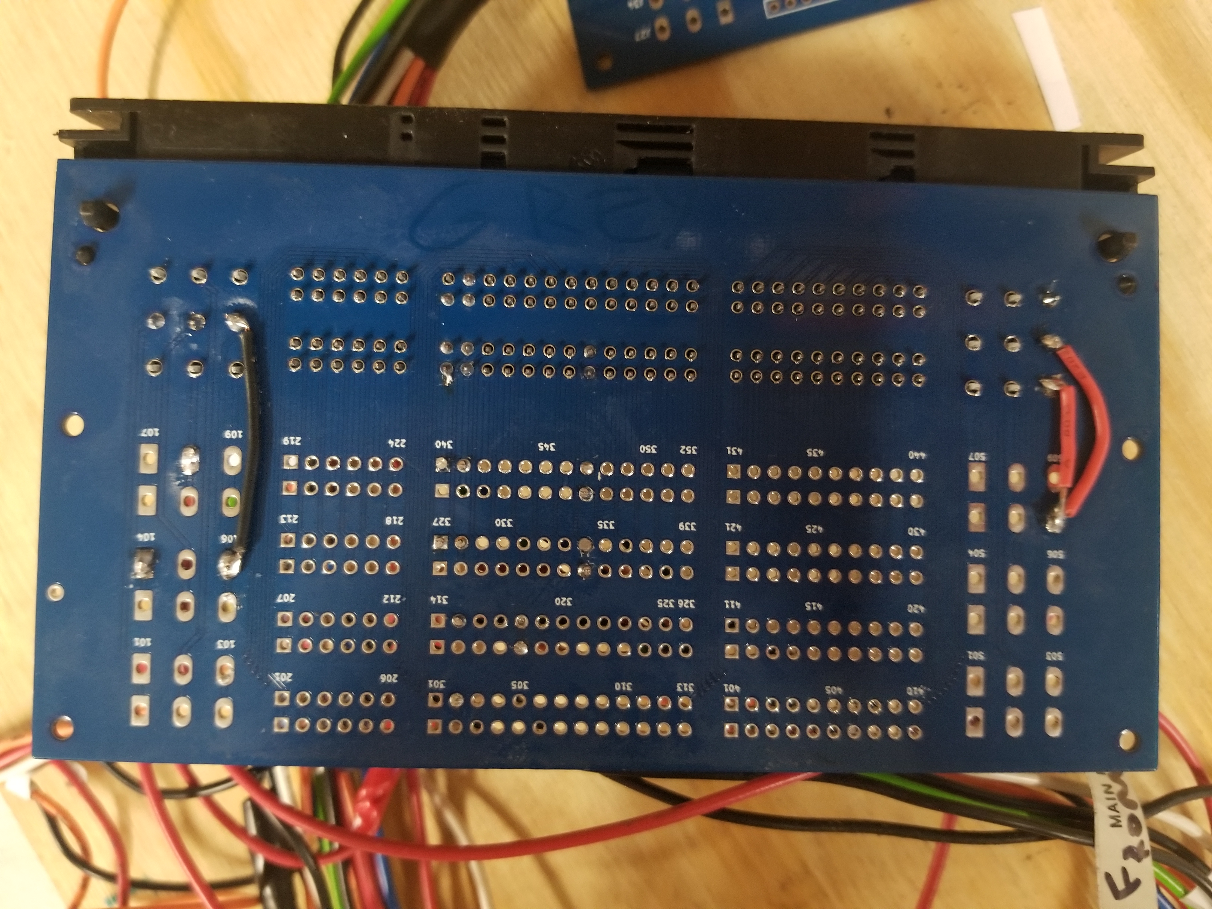
This HOWTO is focusing on M73 engine with stock ECU harness. 1998 stock ECU harness has two 134 pin connectors.
On my 1998 first set of 9+24+52+40+9=134 pins total is BLACK.
Second set of 9+24+52+40+9=134 pins total is GREY.
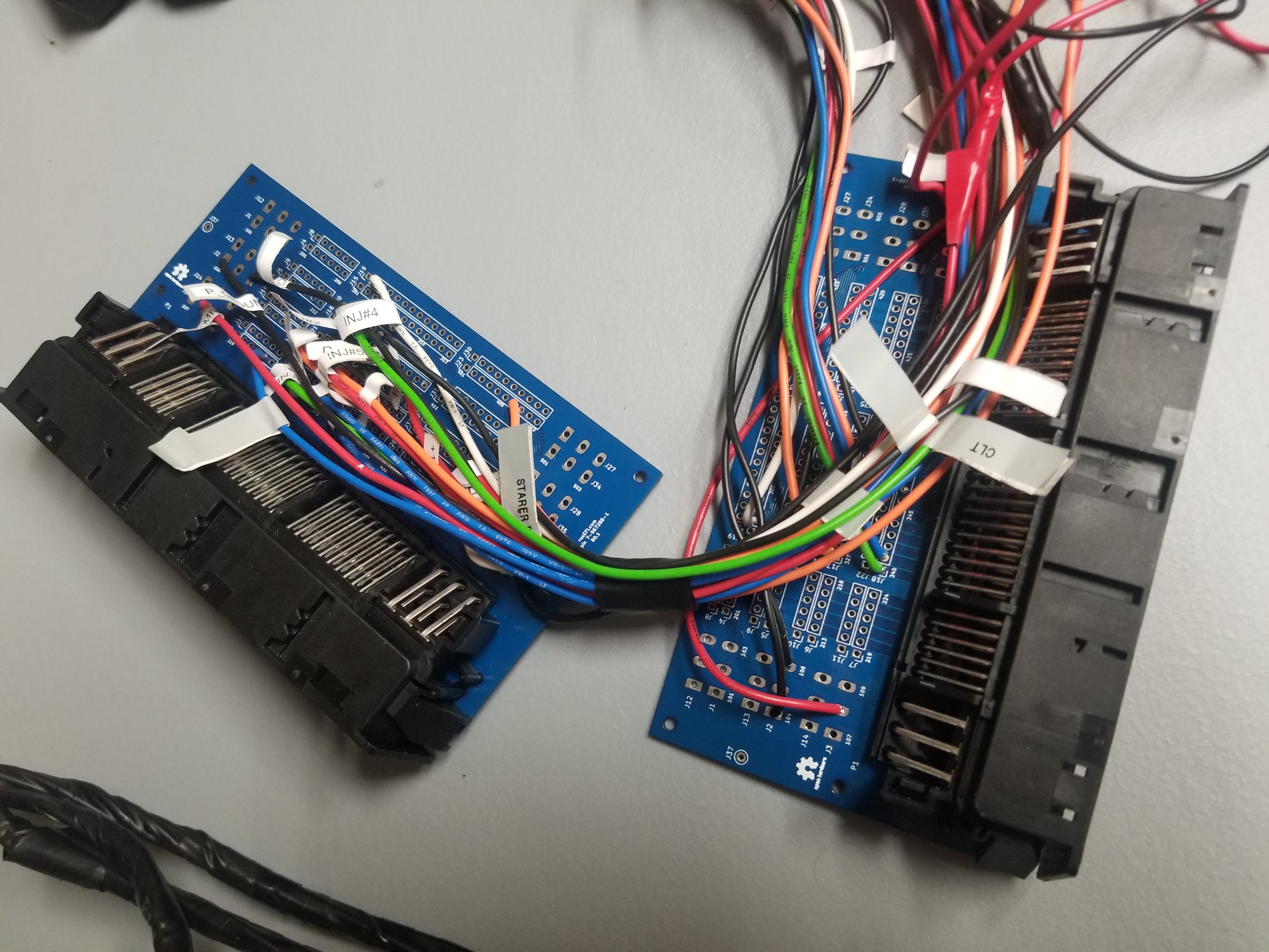
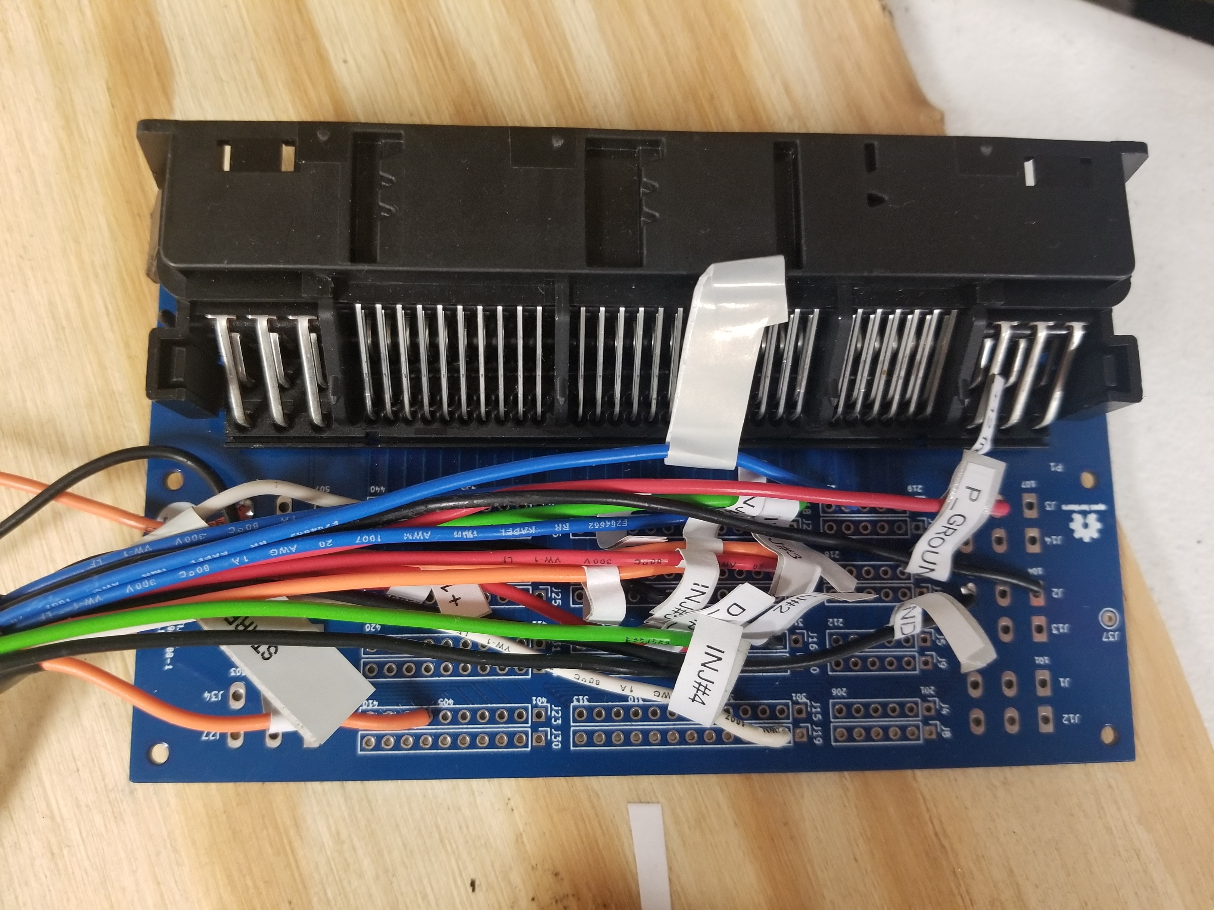
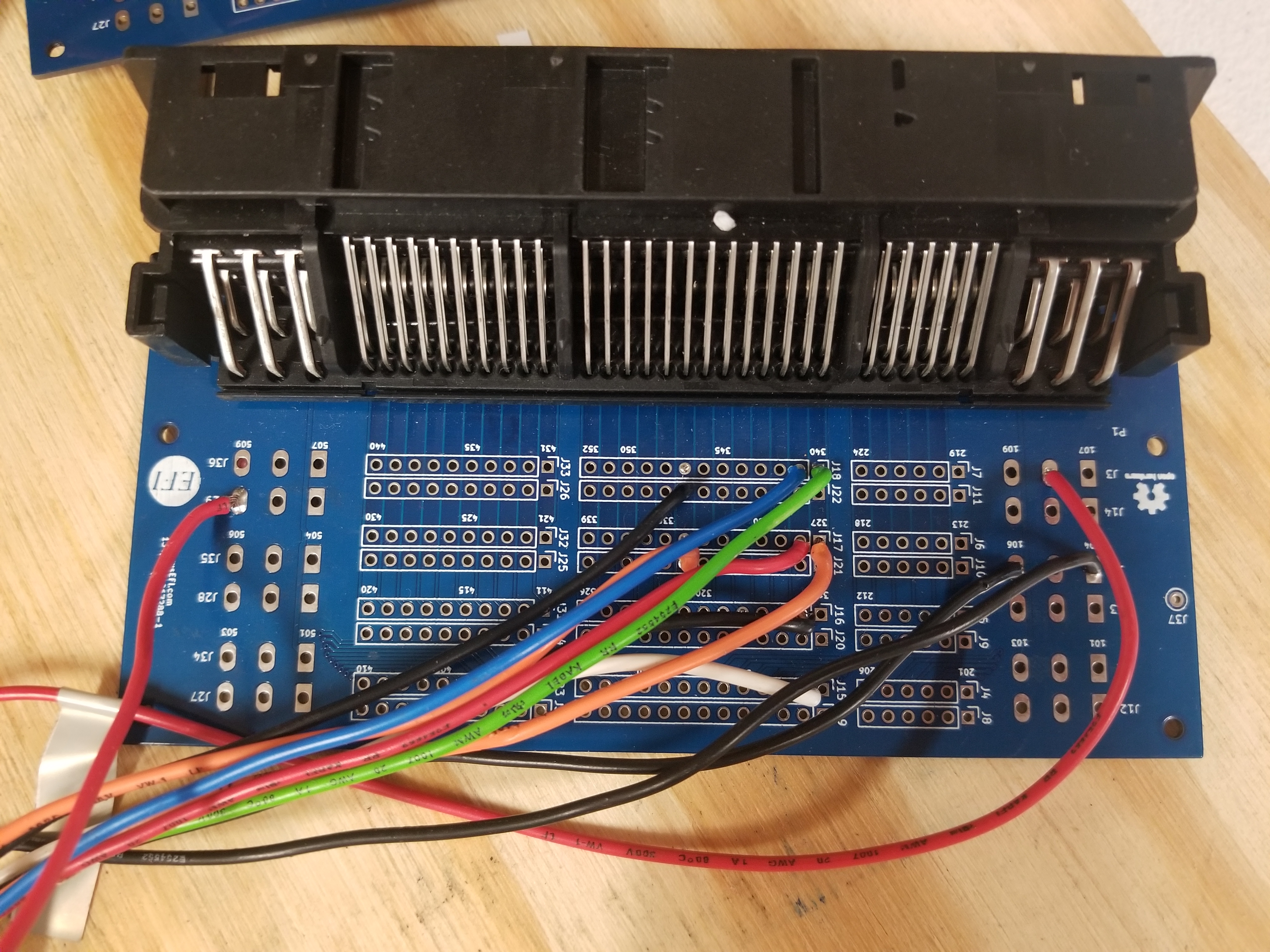
rusEFI uses six wire colors: black white red orange green blue.
Proteus
- +12 from main relay
- x12 injectors
- CLT
- IAT
Destination legend: "Black #3 40/52" means "Black set of ECU plugs, connector #3 - pin 40 of 52 total pins"
Wire length:
ETB/Pedal: 7ft/213cm
Black 35 Pin 776231-1
| Pin Number | Name | Type ID | Default function | rusEFI color | Destination |
|---|---|---|---|---|---|
| 3 | Lowside #1 | ls | Injector #1 | Blue | Black #3 41/52 BRN/WHT |
| 4 | Lowside #3 | ls | Injector #3 | Green | Black #3 40/52 |
| 5 | Lowside #5 | ls | Injector #5 | Red | Black #3 28/52 |
| 6 | Lowside #6 | ls | Injector #6 | Orange | Black #3 27/52 BRN/BLK |
| 7 | Lowside #7 | ls | Injector #7 | Blue | Grey #3 41/52 BRN/WHT |
| 8 | Lowside #9 | ls | Injector #9 | Green | Grey #3 40/52 |
| 9 | Lowside #11 | ls | Injector #11 | Red | Grey #3 28/52 |
| 10 | Lowside #13 | ls | low-side output: main relay | Blue | Black plug #2 23/24 BRN/BLK |
| 11 | Lowside #14 | ls | low-side output: starter enable | White | Black plug #4 40/40 YEL/BRN |
| 15 | Lowside #2 | ls | Injector #2 | Black | Black #3 15/52 |
| 16 | Lowside #4 | ls | Injector #4 | White | Black #3 2/52 |
| 17 | GND | y | Power GND | Black | Grey #1 4/9 |
| 18 | GND | y | Power GND | Black | Black #1 4/9 |
| 19 | Lowside #8 | y | Injector #8 | Black | Grey #3 15/52 |
| 20 | Lowside #10 | y | Injector #10 | White | Grey #3 2/52 |
| 21 | Lowside #12 | y | Injector #12 | Orange | Grey #3 27/52 BRN/BLK |
| 23 | Lowside #16 | y | low-side output: fuel pump | ||
| 24 | GND | y | Power GND | Black | Grey plug #1 6/9 BRN |
| 30 | Ignition 7 | y | Ignition cylinder 7 | White | - |
| 35 | Ignition 1 | y | Ignition cylinder 1 | Orange | - |
Black 23 Pin 776228-1
| Pin Number | Name | Type ID | Default function | rusEFI color | OEM connector |
|---|---|---|---|---|---|
| 1 | DIGITAL 2 | din | Camshaft position sensor | Red | Black plug #3 20/52 |
| 2 | DIGITAL 3 | din | Start signal from ignition key | Orange | Black plug #4 6/40 |
| 5 | VR1 pos | vr | Variable Reluctance #1 positive | Orange | Black #3 32/52 |
| 8 | ETB1- | y | ETB 1 negative | White | |
| 13 | VR1 neg | vr | Variable Reluctance #1 negative | Blue | Black #3 46 /52 |
| 15 | ETB1+ | etb | ETB 1 positive | Blue | |
| 18 | +12 raw | 12v | ignition power / ECU power source | Red | Black plug #4 26/40 GRN/BLK |
| 19 | GND | y | Power GND | Black | Black plug #1 6/9 BRN |
| 21 | ETB2- | etb | ETB 2 negative | White | |
| 22 | ETB2+ | etb | ETB 2 positive | Blue | |
| 23 | +12V mr | 12v | ETB/high-side power supply from main relay | Red | Black #1 8/9 RED/BLU |
White 35 Pin 776231-2
| Pin Number | Name | Type ID | Default function | rusEFI color | OEM connector | . |
|---|---|---|---|---|---|---|
| 1 | GND | sgnd | Sensor GND | Black | Black #3 21/52 BRN | |
| 2 | GND | sgnd | Sensor GND | Black | - | ETB #1 sensor GND |
| 3 | GND | sgnd | Sensor GND | Black | - | ETB #2 sensor GND |
| 4 | GND | sgnd | Sensor GND | Black | Grey #3 47/52 BRN | |
| 5 | GND | sgnd | Sensor GND | Black | - | Throttle Pedal GND |
| 9 | 5V SENS 1 | 5v | Analog Voltage +5 supply #1 | Red | - | ETB #1 sensor feed |
| 10 | 5V SENS 2 | 5v | Analog Voltage +5 supply #2 | Red | - | Throttle Pedal feed |
| 13 | AV1 | av | Analog Voltage Input #1 | |||
| 14 | AV3 | av | Analog Voltage Input #3 | Orange | - | TPS1 Secondary signal |
| 15 | AV5 | av | Analog Voltage Input #5 | Orange | - | TPS2 Secondaryl signal |
| 16 | AV7 | av | Analog Voltage Input #7 | White | - | Pedal Sensor #2 signal |
| 17 | AV9 | av | Analog Voltage Input #9 | |||
| 18 | AV11 | av | Analog Voltage Input #11 | |||
| 24 | AV2 | av | Analog Voltage Input #2 | Green | - | TPS1 Primary signal |
| 25 | AV4 | av | Analog Voltage Input #4 | Green | - | TPS2 Primary signal |
| 26 | AV6 | av | Analog Voltage Input #6 | Green | - | Pedal Sensor #1 signal |
| 27 | AV8 | av | Analog Voltage Input #8 | Blue | MAP/MAF | |
| 28 | AV10 | av | Analog Voltage Input #10 | Green | AFR/WBO | |
| 29 | AV12 | av | Analog Voltage Input #12 | |||
| 30 | AT2 | at | Intake air temperature IAT | Orange | Grey #3 34/52 | |
| 31 | AT4 | at | Coolant temperature CLT | Green | Black #3 22/52 RED/BRN | |
| 32 | 5V SENS 1 | 5v | Analog Voltage +5 supply #1 | Red | - | ETB #2 sensor feed |
| 33 | 5V SENS 2 | 5v | Analog Voltage +5 supply #2 | Red | - |
9 pin plug #1
| Pin Number | Name | Type ID | Default function | rusEFI color | OEM connector |
|---|---|---|---|---|---|
| . | |||||
24 pin plug #2
| Pin | type | OEM color | Description | rusEFI color |
|---|---|---|---|---|
52 pin plug #3
| Pin | type | OEM color | Description | rusEFI color |
|---|---|---|---|---|
40 pin plug #4
| Pin | type | OEM color | Description | rusEFI color |
|---|---|---|---|---|
| 6 | IN | start signal from ignition key | ||
| 17 | OUT | BLK | engine speed output for gauge cluster | |
| 26 | IN | GRN/BLK | RED +12v hot in start & run | |
| 40 | OUT | YEL/BRN | BRN starter enable | |
9 pin plug #5
| Pin | type | OEM color | Description | rusEFI color |
|---|---|---|---|---|
See also https://github.com/rusefi/rusefi/wiki/Vault-Of-Electronic-Throttle-Bodies-ETB