9.1 KiB
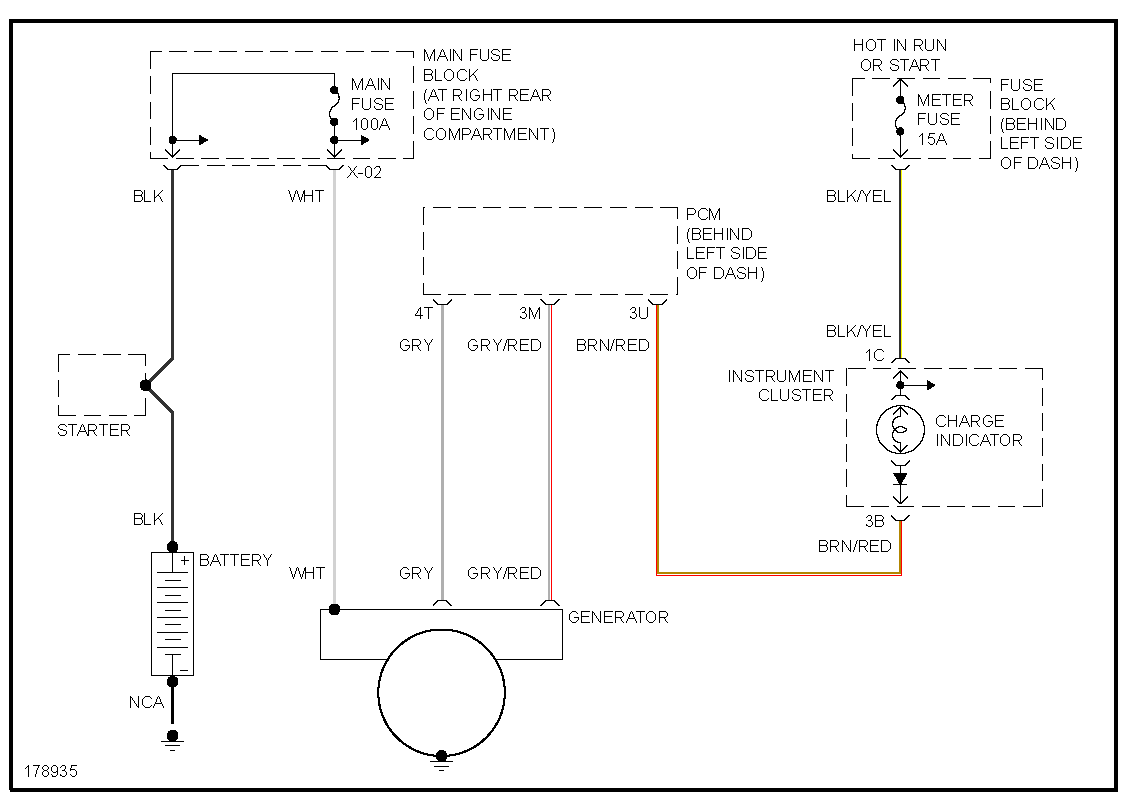
2003 Mazda Miata Alt
In RusEFI console, set engine_type 47 loads base settings.
Wiring
| Pin STM32 | Type | Pin RusEFI | Pin 64 Conn | Pin 72 Conn (NB2) | Desc |
|---|---|---|---|---|---|
| Spare | W1 | 1A | 2P | Idle Pos | |
| Switched 12V | W2 | 1B | 4AF | Main relay Power | |
| Spare | W3 | 1C | 4D | VVT POS | |
| Spare | W4 | 1D | 4S | ECU power | |
| Spare | W5 | 1E | Spare | ||
| PC9 | High side driver | W6 | 1F | 3F | Ignition 1 |
| PE14 | High side driver | W7 | 1G | 3I | Ignition 3 |
| PC7 | High side driver | W8 | 1H | Spare high | |
| PE10 | High side driver | W9 | 1I | 3M | Alternator |
| Spare | W10 | 1J | Spare | ||
| Spare | W11 | 1K | Spare | ||
| PE8 | High side driver | W12 | 1L | 3O | Tacho/Dizzy |
| PE12 | High side driver | W13 | 1M | Spare high | |
| W14 | 1N | Spare | |||
| PD8 | High side driver | W15 | 1O | Spare high | |
| PD9 | High side driver | W16 | 1P | 2R | Check eng |
| Spare | W17 | 1Q | Spare | ||
| Spare | W18 | 1R | Spare | ||
| Spare | W19 | 1S | Spare | ||
| Spare | W20 | 1T | Spare | ||
| Spare | W21 | 1U | Spare | ||
| Spare | W22 | 1V | Spare | ||
| PA5 | CRK 2+ | 2A | |||
| PA5 | Trigger input - | CRK 2- | 2B | 3Y | Crank signal |
| PC6 | CAM + | 2C | |||
| PC6 | Trigger input - | CAM - | 2D | 3V | Cam signal |
| Spare | W27 | 2E | Spare | ||
| Spare | W28 | 2F | Spare | ||
| PB14 | Knock input | W29 | 2G | 4K | Knock |
| PB15 | Knock input | W30 | 2H | ||
| Spare | W31 | 2I | Spare | ||
| Spare | W32 | 2J | Spare | ||
| PB12 | CAN H /RX | W33 | 2K | CAN H | |
| PB6 | CAN L /TX | W34 | 2L | CAN L | |
| PC13 | Low side driver | W35 | 2M | 2Q | Idle solenoid |
| PD7 | Low side driver | W36 | 2N | 3H | Main relay |
| PE5 | Low side driver | W37 | 2O | 2B | Fan |
| PE6 | Low side driver | W38 | 2P | Battery Warning light | |
| GND | Ground | W39 | 3A | 3A | Injector Ground |
| GND | Ground | W40 | 3B | AFR Ground | |
| GND | Ground | W41 | 3C | 3B/4A | Main ground |
| GND | Sensor ground | W42 | 3D | 4O | Sensor ground |
| PC5 | Input | W43 | 3E | Spare input | |
| PC4 | Input | W44 | 3F | Baro input | |
| PA7 | Input | W45 | 3G | Spare input | |
| PA6 | Input | W46 | 3H | Oil pressure sensor input | |
| PA4 | Input | W47 | 3I | WIDEBAND IN | AFR |
| PA3 | Input | W48 | 3J | 4F | Spare input (AC in) |
| 5V | 5V Vref | W49 | 3K | 4L | 5V |
| PA1 | Input | W50 | 3L | 4I | Spare input (clutch) |
| PA2 | Input | W51 | 3M | 4V | TPS |
| PC3 | Input | W52 | 3N | Spare input | |
| PA0 | Input | W53 | 3O | MAP SENSOR IN | MAP |
| PC1 | Input | W54 | 3P | 4O | IAT |
| PC2 | Input | W55 | 3Q | 4P | CLT |
| Spare | W56 | 3R | |||
| PE3 | Low side driver | W57 | 3S | 4R | VVT |
| PE4 | Low side driver | W58 | 3T | 2M | Fuel pump |
| PD3 | Low side driver | W59 | 3U | 2K | A/C Clutch |
| PE2 | Low side driver | W60 | 3V | 2D | Inj 2 |
| PB9 | Low side driver | W61 | 3W | 2A | Inj 1 |
| PD5 | Low side driver | W62 | 3X | 2C | A/C Fan |
| PB8 | Low side driver | W63 | 3Y | 2G | Inj 3 |
| PB7 | Low side driver | W64 | 3Z | 2J | Inj 4 |
Necessary Modifications
Power
ECU gets +12v from main relay output 4AF which is used as +12v source for VVT (4D) and IAC (2P).
Fly-back diode - stripe facing +12 - is needed between VVT 4D (power, stripe side) and VVT control 4R.
Fly-back diode - stripe facing +12 - is needed between IAC 2P (power, stripe side) and IAC control 2Q.
Vehicle Speed Sensor
Vehicle speed sensor (VSS) should be wired internally to P6. P6 is located on the backside of the board near PA8. From there it can be wired to a spare WXX spot on the RusEFI. The NB2 side pin is 3T.
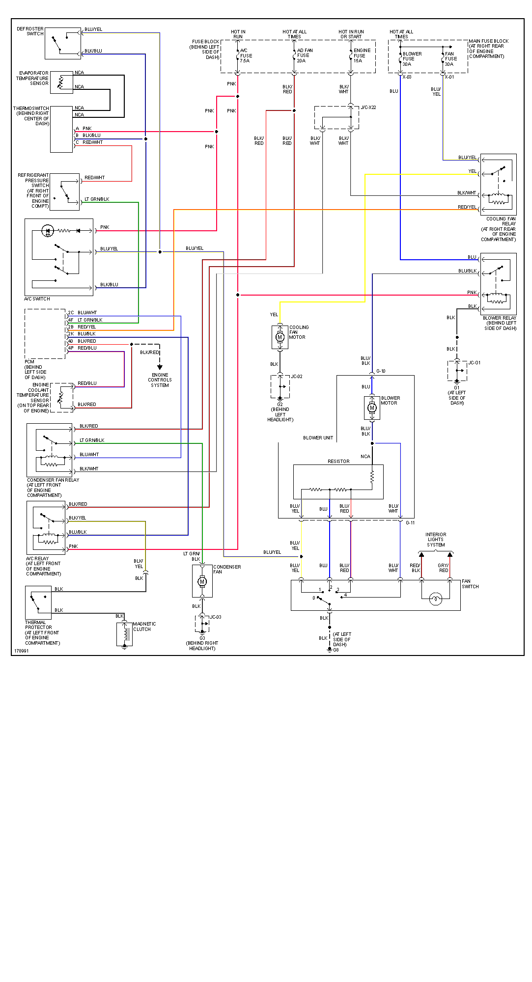
Air Conditioning
| Desc | RusEFI Pin | NB2 Pin |
|---|---|---|
| IN | 3J | 4F |
| FAN | 1O | 2C |
| OUT | 1M | 2K |
IN represents the switch located in the center console.
FAN represents the output to the fan relay in the engine compartment.
OUT represents the output to the A/C Compressor clutch.
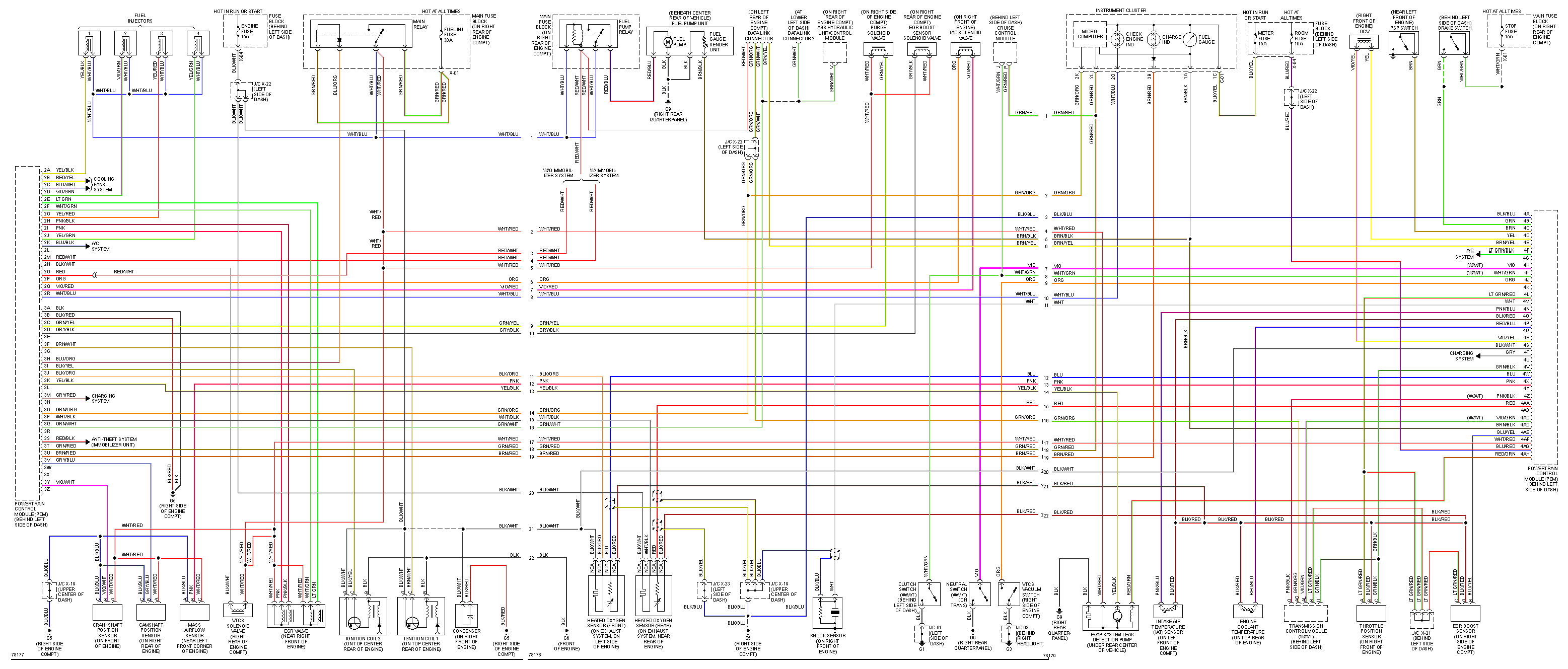
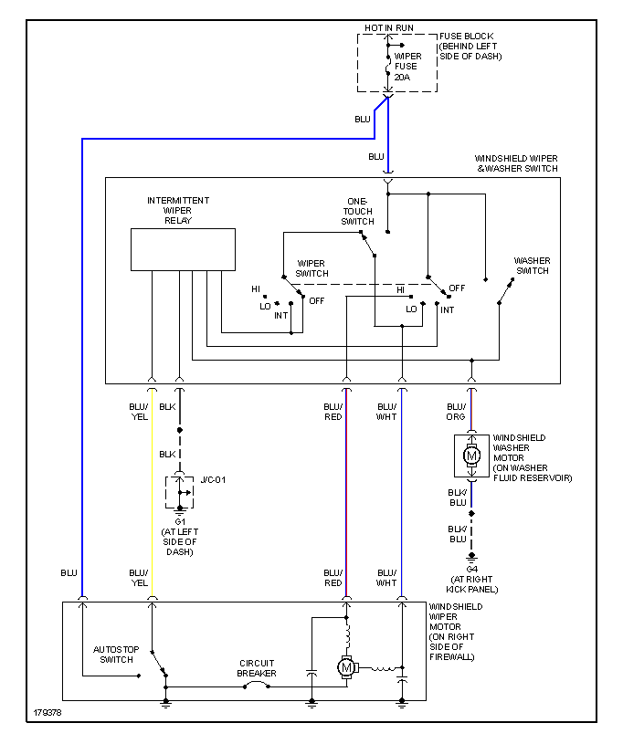
OE Wiring Diagrams
Individual pages for printing:

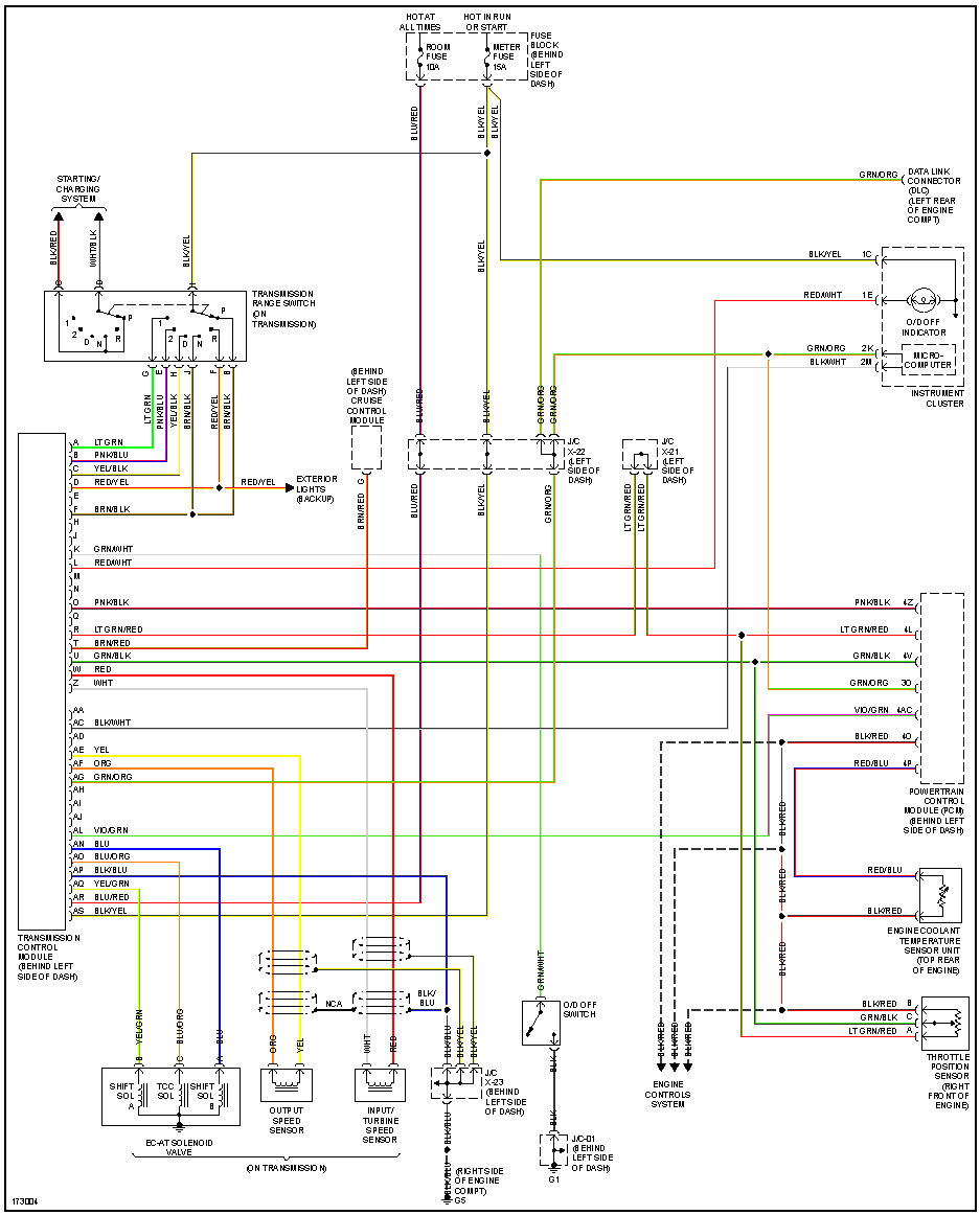
Automatic Transmission
see Mazda Miata 2001 - Automatic Transmission
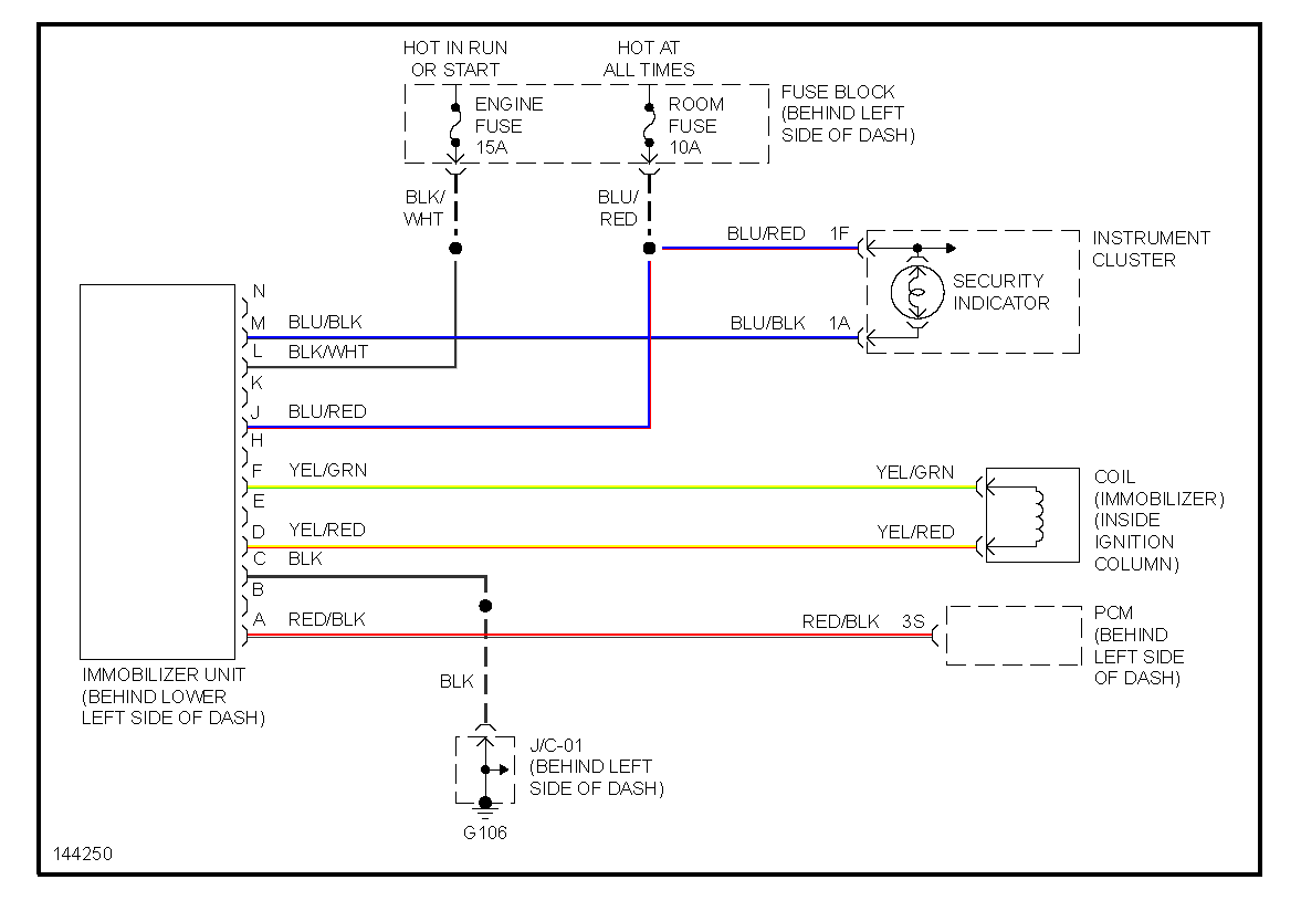
Immobilizer
NALDEC NC87 67 790 MAZDA MX5 EUNOS MK2 MK2.5 BURGLAR ALARM MODULE NC8767790 is not an immobilizer


