2.8 KiB
2.8 KiB
~6 wires are different between Proteus 0.2 and Proteus 0.3
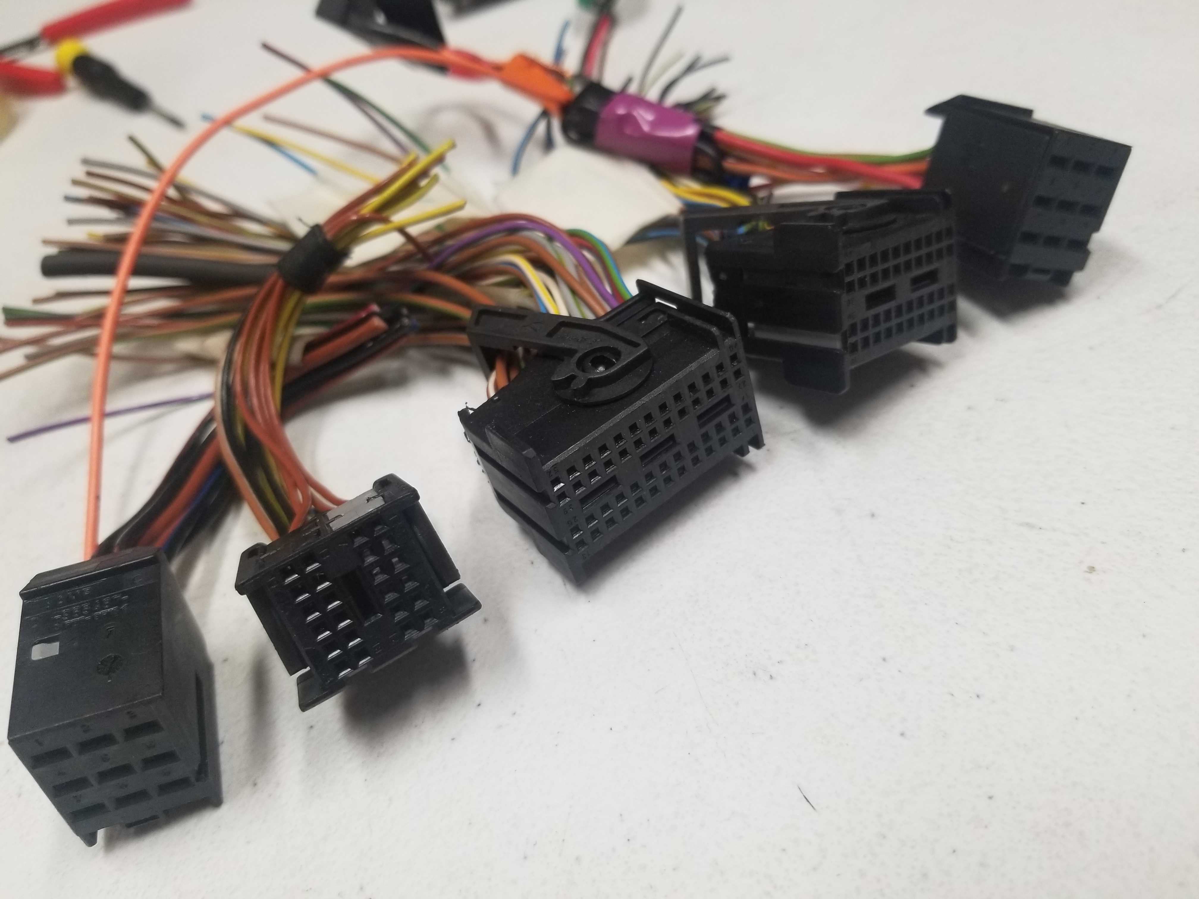
This HOWTO is focusing on M73 engine with stock ECU harness. 1998 stock ECU harness has two 134 pin connectors.
On my 1998 first set of 9+24+52+40+9=134 pins total is BLACK.
Second set of 9+24+52+40+9=134 pins total is GREY.
rusEFI uses six wire colors: black white red orange green blue.
9 pin plug #1
| Pin | type | OEM color | Description | rusEFI color |
|---|---|---|---|---|
24 pin plug #2
| Pin | type | OEM color | Description | rusEFI color |
|---|---|---|---|---|
52 pin plug #3
| Pin | type | OEM color | Description | rusEFI color |
|---|---|---|---|---|
40 pin plug #4
| Pin | type | OEM color | Description | rusEFI color |
|---|---|---|---|---|
| 6 | IN | start signal from ignition key | ||
| 17 | OUT | BLK | engine speed output for gauge cluster | |
| 26 | IN | GRN/BLK | RED +12v hot in start & run | |
| 40 | OUT | YEL/BRN | BRN starter enable | |
9 pin plug #5
| Pin | type | OEM color | Description | rusEFI color |
|---|---|---|---|---|
Proteus
- +12 from main relay
- x12 injectors
- CLT
- IAT
Black 35 Pin 776231-1
| Pin Number | Name | Type ID | Default function | rusEFI color | Destination |
|---|---|---|---|---|---|
| 3 | Lowside #1 | ls | Injector #1 | ||
| 4 | Lowside #3 | ls | Injector #3 | ||
| 5 | Lowside #5 | ls | Injector #5 | ||
| 6 | Lowside #6 | ls | Injector #6 | ||
| 7 | Lowside #7 | ls | Injector #7 | ||
| 8 | Lowside #9 | ls | Injector #9 | ||
| 9 | Lowside #11 | ls | Injector #11 | ||
| 10 | Lowside #13 | ls | low-side output: main relay | Blue | Black plug #2 23/24 BRN/BLK |
Black 23 Pin 776228-1
| Pin Number | Name | Type ID | Default function | rusEFI color | OEM connector |
|---|---|---|---|---|---|
| 18 | +12 raw | 12v | ignition power / ECU power source | Red | Black plug #4 26/40 GRN/BLK |
| 19 | GND | y | Power GND | Black | Black plug #1 6/9 BRN |
| 23 | +12V mr | 12v | ETB/high-side power supply from main relay | Red | Black #1 8/9 RED/BLU |