5.9 KiB
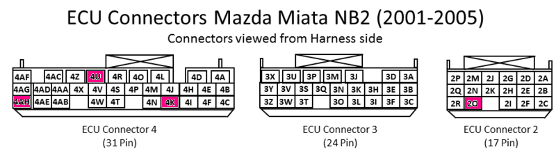
Mazda Miata MX5 NB2 2001-2005 Standalone
microRusEFI should be set for Hall
High-side jumper should be set for +12v.
Some versions of Miata may need a jumper set on the board, See detail here
https://rusefi.com/forum/viewtopic.php?t=1677
https://rusefi.com/wiki/index.php?title=Vehicle:Mazda_Miata_2002
https://rusefi.com/wiki/index.php?title=Vehicle:Mazda_Miata_2003
https://github.com/rusefi/rusefi/wiki/Hardware/pnp_microRusEfi_nb2/hw72nb.pdf
| Pin Number | Name | microRusEFI pin | Type ID | Default function |
|---|---|---|---|---|
| 2A | Inj 1 | #37 | Low-Side | Injector #1 |
| 2B | Fan | #34 | Low-Side | Radiator Fan Control Relay Output |
| 2C | A/C Fan | #43 | Low-Side | A/C Fan Control Relay Output |
| 2D | Inj 2 | #38 | Low-Side | Injector #2 |
| 2G | Inj 3 | #41 | Low-Side | Injector #3 |
| 2J | Inj 4 | #42 | Low-Side | Injector #4 |
| 2O | rusEFI WBO | x | x | |
| 2M | Fuel Pump | #35 | Low-Side | Fuel Pump Relay Output |
| 2P | IAC Feed | 12V | Idle Valve Power | |
| 2Q | IAC Control | #3 | Low-Side | Idle Valve Control |
| 2R | MIL | #33 | Low-Side | Check Engine Light output |
| - | - | - | - | - |
| 3A | GND | #2 | Power Ground | Ground |
| 3B | GND | #6 | Power Ground | Ground |
| 3F | Coil #1 | #9 | High-Side | Coil #1 control |
| 3I | Coil #2 | #11 | High-Side | Coil #2 control |
| 3H | Main Relay | #29 | Low-Side | Main Relay Control |
| 3K | rusEFI USB PWR | x | x | |
| 3L | rusEFI CAN H | x | x | |
| 3M | Alternator | #13 | High-Side | Alternator Control Output |
| 3N | rusEFI CAN L | x | x | |
| 3O | Tach | #14 | High-Side | Tachometer Output |
| 3V | Cam | #25 | Hall Input | Cam shaft Hall Input |
| 3U | Alt Warn | x | x | |
| 3Y | Crank | #45 | Hall Input | Crank shaft Hall Input |
| 3Z | rusEFU USB GND | x | x | |
| - | - | - | - | |
| 4A | GND | Ground | Ground | |
| 4D | VVT Feed | 12V | VVT Power | |
| 4K | rusEFI 5v out | #39 | 5v | External MAP sensor power |
| 4L | rusEFI 5v out | #44 | 5v | Throttle Position Sensor Power |
| 4N | IAT | #23 | AT | Intake Air Temperature Sensor |
| 4O | GND | GND | Sensor Ground | |
| 4P | CLT | #18 | Temp Input | Coolant Temperature Sensor Input |
| 4R | VVT | #7 | Low-side | VVT Control |
| 4S | Key | #5 | 12V | +12v from Ignition Key |
| 4V | TPS | #26 | AV | Throttle Position Sensor |
| 4X | MAF not routed | x | x | |
| 4AE | EGR Boost Sensor | AV | MAP | |
| 4AF | Main Relay Power | #1 | 12V | +12v from Main Relay |
| xx | x | x | x |
x4 AUX low-side drivers
There are 4 low-side drivers available. One is used for the alternator warning light on the dash. The following I/O is available. A jumper wire will need to be routed between the Jx hole on the board and the appropriate pin on the car-side connector.
| Board | stm32 pin | |
|---|---|---|
| J3 | PB8 | |
| J1 | PB9 | |
| J2 | PC12 |
Extra pins for 353830-5 72 pin:
TE 316836-1 for 20 AWG to 22 AWG
TE 316838-1 for 16 - 18 AWG
Note the latch on OEM ECU plugs while installing add-on pins.
MREAdapter72 0.2 InteractiveBOM
OEM harness add-ons
| Board | stm32 pin | |
|---|---|---|
| 3L | AFR | Analog signal for external wide band oxygen controller |
| 4U | MAP | Manifold absolute pressure analog signal from external sensor |
| 4K | +5v | +5v feed for MAP sensor |
| 3Z | GND | Sensor & USB ground |
Adapter Board Wiring
| Connector | microRusEFI | |
|---|---|---|
SD card wiring
| Board | stm32 pin | |
|---|---|---|
| PC10 | SD card SPI Clock | |
| PC11 | SD card SPI MISO | |
| PC12 | SD card SPI MOSI | |
| PB8 | SD card SPI Chip Select |
Bluetooth/TTL wiring
| Board | stm32 pin | |
|---|---|---|
| PC10 | ||
| PC11 |
Photos
https://github.com/rusefi/rusefi/wiki/Hardware/pnp_microRusEfi_nb2/MREAdapter72_0_2_front.jpg https://github.com/rusefi/rusefi/wiki/Hardware/pnp_microRusEfi_nb2/MREAdapter72_0_2_back.jpg
Case compatibility:
Toyota Camry 89661-3T270
Toyota Camry 89661-06691