1.2 KiB
1.2 KiB
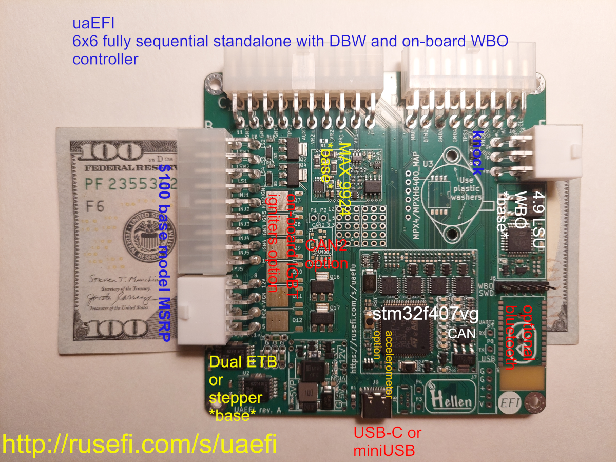
Ultra Affordable EFI
Features
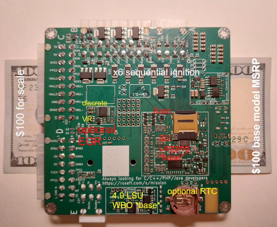
- sequential six smart coils with option of on-board igniters
- sequential six injector outputs
- two VRs: one MAX9924 one vr-discrete, both with solder-blob jumper to modify into hall input
- two hall inputs
- dual DC motor to drive dual DWB or ETB+wastegate or stepper idle
- on-board 4.9 LSU WBO controller
- on-board SD card
- up to two CAN buses
- on-board baro sensor
- four above 1A current low side outputs
- a couple of lower current low side outputs
- flex fuel input
- knock sensor input
- on-board real time clock battery
- on-board MAP sensor footprints
- on-board EGT input
- proto area
- 100x100mm 4 layer PCB
Harness Connectors
- A 39012080 or 39012085
- B 39012180 or 39012185
- C 39012200 or 39012205
- D 39012160 or 39012165
- E 39012060 or 39012065
PCB headers
- A 5569-08A2 39300080 39301080
- B 5569-18A2 39301180
- C 5569-20A2 39301200
- D 5569-16A2 39301160
- E 5569-06A2 39301060

