5.9 KiB
| title | description | published | date | tags | editor | dateCreated |
|---|---|---|---|---|---|---|
| CanBus Support | true | 2022-12-30T07:24:55.946Z | undefined | 2020-12-15T21:58:51.731Z |
Overview
Speeduino is able to support Canbus in two ways.
- Use a Mega2560 MCU with a coprocessor board
- Use a Teensy or STM32 (with internal can module) MCU.
The Teensy3.5 uses pins 3(Tx) and 4(RX) for connection to the can transceiver. The Teensy3.6 uses pins 3(Tx) and 4(RX) for can0 and 33(TX) and 34(RX) for can1 for connection to the can transceivers. The STM32F4XX uses pins PD0(RX) and PD1(TX) by default for can0 and PB5(RX) and PB6(TX) for can1 for connection to the can transceivers. {.is-info}
About the CanBus Interface
The can0 Canbus Interface offers ,
- OBD2 formatted data of current realtime data .
- Broadcast selected current realtime data and function status .(coming soon)
- Read in Analog and Digital data values from other devices on the BUS including those from OEM devices/ECU.(coming soon).
- Connect to Tunerstudio for programming/data logging.(under development)
draft note: under development The can1 Canbus Interface offers ,
- Broadcast current realtime data and function status
- Read in Analog and Digital data values from other devices on the BUS including those from OEM devices/ECU.
- Connect to Tunerstudio for programming/data logging.
Settings
Enable CanBus interface
To enable use of the Canbus interface it must be enabled in TunerStudio.
OBD2 Data Support
When used with an MCU that has an Internal canbus interface Speeduino firmware is able to output data using the OBD2 std On MCU that have multiple canbus ports the OBD support is provided on can0.
Speeduino does not offer “readiness monitoring” or emission testing support and should not be used for such. {.is-warning}
OBD Port Interface Configuration
The Interface supports 11bit addressing @500kbps data rate. The port will respond to the STD OBD2 protocol . Any code reader /app /software following OBD2 standard protocol is able to access the data described below.
OBD Port Interface Support Options
The OBD2 port Interface offers support for ,
-
To output the current realtime data (see supported PID list) .
-
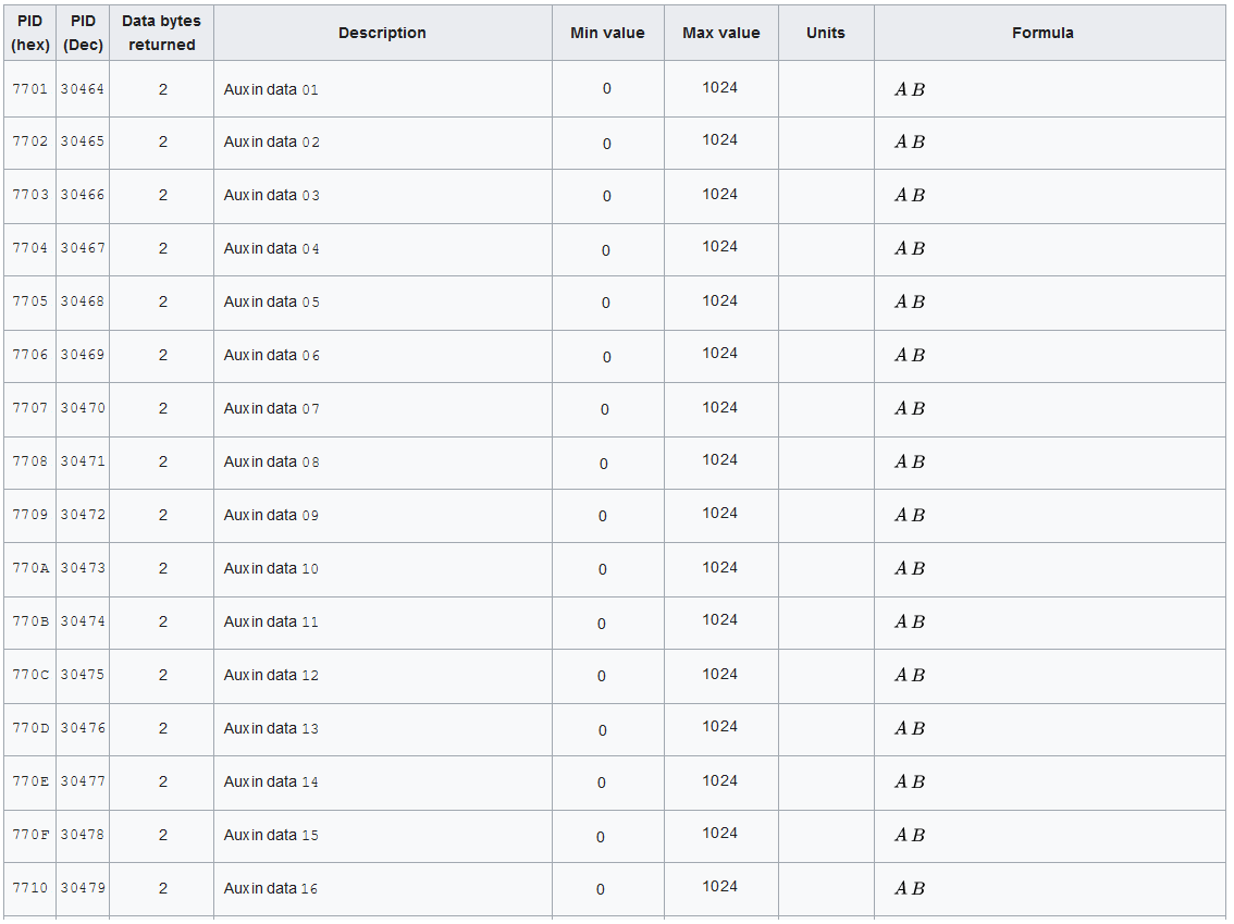
Output the Analog/Digital data values from the 16 Aux inputs (see here for info on aux data input configuration)
-
Activate External Outputs(coming soon!)
Modes Supported
There are 10 diagnostic services described in the latest OBD-II standard SAE J1979. Before 2002, J1979 referred to these services as "modes". Speeduino supports only a selected number of these modes. These are:
Mode (hex) Description
- 01 Show current data
- 09 Vehicle information (VIN) (coming soon)
- 22 Manufacturer Specific data.
Mode 22 is a custom PID mode that is defined by the manufacturer. It is used to define additional services.
PID supported
The following PIDs are supports by by the OBD port
When using Bit-Encoded-Notation, quantities like C4 means bit 4 from data byte C. Each bit is numerated from 0 to 7, so 7 is the most significant bit and 0 is the least significant bit (See below).

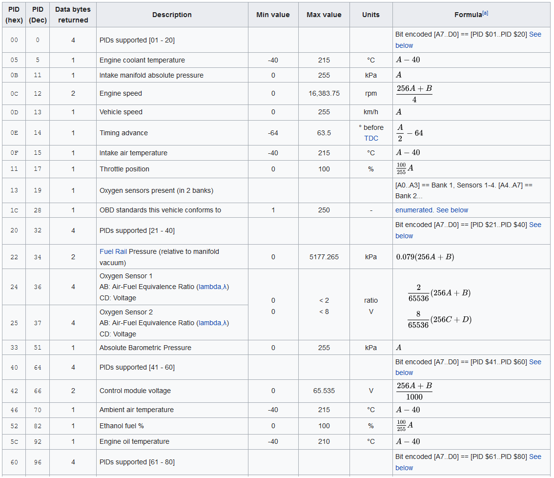
MODE 01
The table below shows the current list of PIDs supported by the firmware (as of 16/12/2020). {.is-info}
MODE 9
Mode 9 support is coming soon!
MODE 22
Speeduino responds to the Mode 22 request for the following PID:
Bitwise encoded PIDs
Some of the PIDs in the above table cannot be explained with a simple formula. A more elaborate explanation of these data is provided here: Example MODE 01 PID 00
A request for this PID returns 4 bytes of data (Big-endian). Each bit, from MSB to LSB, represents one of the next 32 PIDs and specifies whether that PID is supported.
For example, if the car response is BE1FA813, it can be decoded like this:

So, supported PIDs are: 01, 03, 04, 05, 06, 07, 0C, 0D, 0E, 0F, 10, 11, 13, 15, 1C, 1F and 20
CAN (11-bit) bus format
The PID query and response occurs on the vehicle's CAN bus. Standard OBD requests and responses use functional addresses. The diagnostic reader initiates a query using CAN ID 7DFh, which acts as a broadcast address, and accepts responses from any ID in the range 7E8h to 7EFh. ECUs that can respond to OBD queries listen both to the functional broadcast ID of 7DFh and one assigned ID in the range 7E0h to 7E7h. Their response has an ID of their assigned ID plus 8 e.g. 7E8h through 7EFh.
This approach allows up to eight ECUs, each independently responding to OBD queries. The diagnostic reader can use the ID in the ECU response frame to continue communication with a specific ECU. In particular, multi-frame communication requires a response to the specific ECU ID rather than to ID 7DFh.
CAN bus may also be used for communication beyond the standard OBD messages. Physical addressing uses particular CAN IDs for specific modules (e.g., 720h for the instrument cluster in Fords) with proprietary frame payloads.
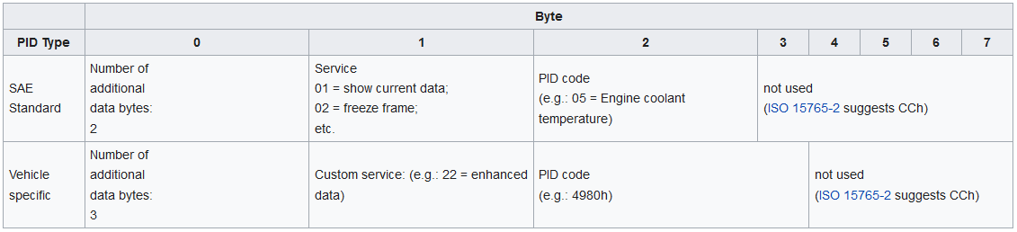
Query
The functional PID query is sent to the vehicle on the CAN bus at ID 7DFh, using 8 data bytes. The bytes are:
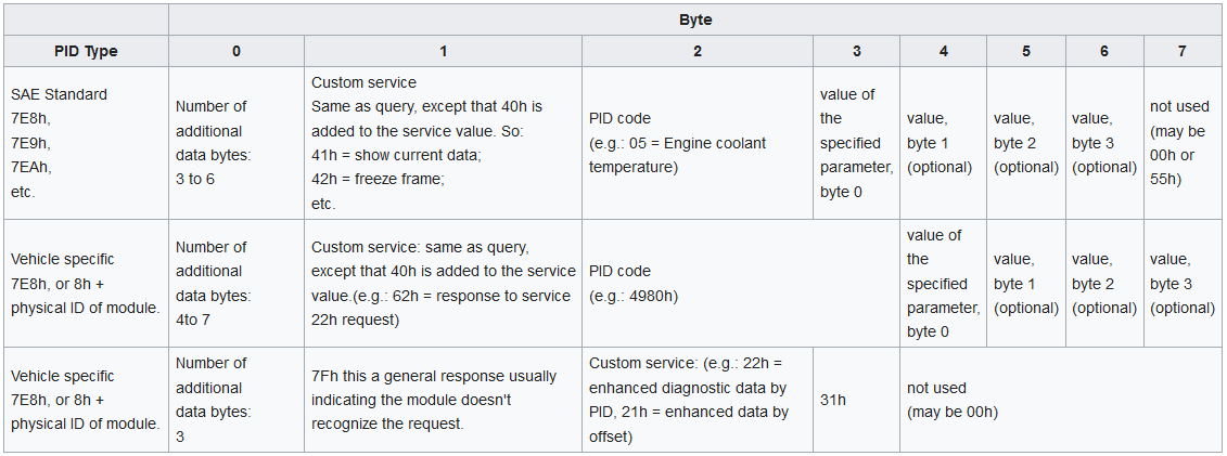
Response
The vehicle responds to the PID query on the CAN bus with message IDs that depend on which module responded. Typically the engine or main ECU responds at ID 7E8h. Other modules, like the hybrid controller or battery controller in a Prius, respond at 07E9h, 07EAh, 07EBh, etc. These are 8h higher than the physical address the module responds to. Even though the number of bytes in the returned value is variable, the message uses 8 data bytes regardless (CAN bus protocol form Frameformat with 8 data bytes). The bytes are: