14 KiB
| title | description | published | date | tags | editor | dateCreated |
|---|---|---|---|---|---|---|
| Secondary Serial IO interface | true | 2023-02-22T16:44:14.084Z | undefined | 2020-01-06T01:37:19.933Z |
Overview
The Arduino Mega2560 version of Speeduino supports the use of Serial3 for supplemetry IO. The STM32F4XX and Teensy3.5/6 versions use Serial2 . On a Mega 2560 Serial3 can be found on the board at pins 14 and 15 - these are not broken out to the IDC connector on the 0.3 or 0.4 boards. The connection speed is 115200baud, 8 bits, parity none and 1 stop bit. Supplementry IO via Canbus is under development for Teensy and Mega2560 mcu types. The use of canbus will also enable more advanced features to be added in the future.
Settings
Enable Secondary IO interface
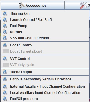
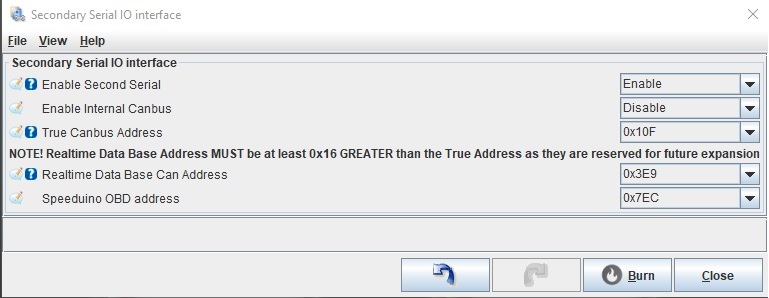
To enable use of the Secondary io interface it must be enabled in TunerStudio.
Dependant on if CAN_COMMANDS have been enabled will vary the type of dropdown menu you will see
select option "Secondary Serial IO Interface" or "CanBus/Secondary Serial IO Interface" as appropriate.
Secondary IO Configuration Options
Again dependant on if CAN_COMMANDS have been enabled will vary what options you have to enable Secondary serial.
- Enable options
-
- Disabled
-
- Enabled Secondary IO via Serial port
-
- Enabled Secondary IO via canbus (this option will only be available when CAN_COMMANDS are enabled
How to use it
Depending on if the secondary port is a simple serial port or is a canbus port there are several things that the Secondary io interface is capable of.
A Simple Serial Port
A Serial port offers ,
- Retrieve the current realtime data from Speeduino . This can be a simple or full(enhanced) data set. This is the same realtime data as sent to TunerStudio.
- Retrieve specific current realtime data from Speeduino.
- Read in the Analog data values from 16 remote sensors as requested by Speeduino.
- Activate External Outputs(coming soon!)
A Canbus Port
A Canbus port offers ,
- OBD2 formatted data of current realtime data .
- Broadcast selected current realtime data and function status .(COMING SOON!)
- Read in Analog and Digital data values from other devices on the BUS including those from OEM devices/ECU.(COMING SOON!)
Serial Port Functions
Retrieve realtime data
To get Speeduino to send out the realtime data to your device connected on a Secondary Serial IO port you must send either an "A", an "n" or an "r" to it. An 'A' will retreive a simple set of data whereas an 'n' will retreive an enhanced set of realtime data. An 'r' will retrieve specific data starting at a selected position in the list for x number of bytes.
- Send an "A"
If you send an "A" to the port it will reply with ,
- A "A" confirming the received instruction (sent as 0x41 in hex),
- The port will then transmit the first 75 realtime data values from the list below(simple data set).
The "A" command data set will not be changed or expanded upon and is maintained for legacy devices. Designers of new devices are recommended to use the newer "n" command to enable use of any additonal enhanced realtime data available beyond the orignal 75 This command supports.
- Send an "n"
If you send an "n" to the Serial port it will reply with,
- A "n" confirming the received instruction (sent as 0x6E in hex (110 in DEC) ).
- A single hex byte ,this value is the type of "n" command about to be sent. In this case the value is 0x32 in Hex.
- A single hex byte , this value is the number of data bytes the port will be transmitting next as part ofthe command. At the time of writing (09/07/2021) this is 0x77 (119 dec)
- The port will now transmit the realtime data.
- Send an "r"
if you send an "r" to the port you must also send 6 further additional bytes immediately after the "r". These are the Speeduino TS canID, The r type command 0x30(48 in decimal), A 2 byte offset and a 2 byte length. the offset is the position in the realtime list you want the data returned to start from and the 2 byte length is the number of bytes you want returned. the bytes are sent LSB first .
The port will reply with ,
- A "r" confirming the received instruction (send as 0x72 in hex).
- The port will now transmit a single byte in hex ,this is the type of the "r" type command about to be sent,This confirms what was requested (this is typically 0x30).
- The port will then transmit the realtime data requested starting at the byte position set by the offset value for the number of bytes set by the length value.
- ' The Realtime Data List'
As of 23/02/2020 the data list is as follows
BIT 0 - currentStatus.secl
secl is simply a counter that increments each second
1 - currentStatus.status1
Status1 Bitfield(was squirt)
inj1Status(0), inj2Status(1),inj3Status(2), inj4Status(3), DFCOOn(4), boostCutFuel(5), toothLog1Ready(6), toothLog2Ready(7)
2 - currentStatus.engine
Engine Status Bitfield
running(0), crank(1), ase(2), warmup(3), tpsacden(5), mapaccden(7)
3 - (byte)(divu100(currentStatus.dwell))
Dwell in ms * 10
4 - lowByte(currentStatus.MAP)
5 - highByte(currentStatus.MAP)
6 - (byte)(currentStatus.IAT + CALIBRATION_TEMPERATURE_OFFSET)
mat
7 - (byte)(currentStatus.coolant + CALIBRATION_TEMPERATURE_OFFSET)
Coolant ADC
8 - currentStatus.batCorrection
Battery voltage correction (%)
9 - currentStatus.battery10
battery voltage
10 - currentStatus.O2;
primary O2
11 - currentStatus.egoCorrection
Exhaust gas correction (%)
12 - currentStatus.iatCorrection
Air temperature Correction (%)
13 - currentStatus.wueCorrection
Warmup enrichment (%)
14 - lowByte(currentStatus.RPM)
rpm LB
15 - highByte(currentStatus.RPM)
rpm HB
16 - currentStatus.TAEamount
acceleration enrichment (%)
17 - currentStatus.corrections
Total GammaE (%)
18 - currentStatus ve
Current VE 1 (%)
19 - currentStatus.afrTarget
chosen afr target
20 - lowByte(currentStatus.PW1)
Pulsewidth 1 multiplied by 10 in ms. Have to convert from uS to mS.
21 - highByte(currentStatus.PW1);
Pulsewidth 1 multiplied by 10 in ms. Have to convert from uS to mS.
22 - currentStatus.tpsDOT
TPS DOT
23 - currentStatus.advance
Current spark advance
24 - currentStatus.TPS
TPS (0% to 100%)
25 - lowByte(currentStatus.loopsPerSecond)
loops per second LB
26 - highByte(currentStatus.loopsPerSecond)
loops per second HB
27 - lowByte(currentStatus.freeRAM)
freeRam LB
28 - highByte(currentStatus.freeRAM)
freeRam HB
29 - currentStatus.boostTarget
Target boost pressure
30 - currentStatus.boostDuty
current pwm boost dutycycle
31 - currentStatus.spark
Spark related bitfield
launchHard(0), launchSoft(1), hardLimitOn(2), softLimitOn(3), boostCutSpark(4), error(5), idleControlOn(6), sync(7)
32 - lowByte(currentStatus.rpmDOT)
rpmDOT must be sent as a signed integer
33 - highByte(currentStatus.rpmDOT)
rpmDOT HB
34 - currentStatus.ethanolPct
Flex sensor value (or 0 if not used)
35 - currentStatus.flexCorrection
Flex fuel correction (% above or below 100)
36 - currentStatus.flexIgnCorrection
Ignition correction (Increased degrees of advance) for flex fuel
37 - currentStatus.idleLoad
idleload
38 - currentStatus.testOutputs
testoutputs bitfield
testEnabled(0), testActive(1)
39 - currentStatus.O2_2
Second O2
40 - currentStatus.baro
Barometer value
41 - lowByte(currentStatus.canin[0]);
42 - highByte(currentStatus.canin[0]);
43 - lowByte(currentStatus.canin[1]);
44 - highByte(currentStatus.canin[1]);
45 - lowByte(currentStatus.canin[2]);
46 - highByte(currentStatus.canin[2]);
47 - lowByte(currentStatus.canin[3]);
48 - highByte(currentStatus.canin[3]);
49 - lowByte(currentStatus.canin[4]);
50 - highByte(currentStatus.canin[4]);
51 - lowByte(currentStatus.canin[5]);
52 - highByte(currentStatus.canin[5]);
53 - lowByte(currentStatus.canin[6]);
54 - highByte(currentStatus.canin[6]);
55 - lowByte(currentStatus.canin[7]);
56 - highByte(currentStatus.canin[7]);
57 - lowByte(currentStatus.canin[8]);
58 - highByte(currentStatus.canin[8]);
59 - lowByte(currentStatus.canin[9]);
60 - highByte(currentStatus.canin[9]);
61 - lowByte(currentStatus.canin[10]);
62 - highByte(currentStatus.canin[10]);
63 - lowByte(currentStatus.canin[11]);
64 - highByte(currentStatus.canin[11]);
65 - lowByte(currentStatus.canin[12]);
66 - highByte(currentStatus.canin[12]);
67 - lowByte(currentStatus.canin[13]);
68 - highByte(currentStatus.canin[13]);
69 - lowByte(currentStatus.canin[14]);
70 - highByte(currentStatus.canin[14]);
71 - lowByte(currentStatus.canin[15]);
72 - highByte(currentStatus.canin[15])
73 - currentStatus.tpsADC
TPS (Raw 0-255)
74 - getNextError()
Error codes
errorNum(0:1), currentError(2:7)
75 - currentStatus.launchCorrection
76 - lowByte(currentStatus.PW2)
Pulsewidth 2 multiplied by 10 in ms. Have to convert from uS to mS.
77 - highByte(currentStatus.PW2)
Pulsewidth 2 multiplied by 10 in ms. Have to convert from uS to mS.
78 - lowByte(currentStatus.PW3)
Pulsewidth 3 multiplied by 10 in ms. Have to convert from uS to mS.
79 - highByte(currentStatus.PW3)
Pulsewidth 3 multiplied by 10 in ms. Have to convert from uS to mS.
80 - lowByte(currentStatus.PW4)
Pulsewidth 4 multiplied by 10 in ms. Have to convert from uS to mS.
81 - highByte(currentStatus.PW4)
Pulsewidth 4 multiplied by 10 in ms. Have to convert from uS to mS.
82 - currentStatus.status3
resentLockOn(0), nitrousOn(1), fuel2Active(2), vssRefresh(3), halfSync(4), nSquirts(6:7)
83 - currentStatus.engineProtectStatus
RPM(0), MAP(1), OIL(2), AFR(3), Unused(4:7)
84 - lowByte(currentStatus.fuelLoad)
85 - highByte(currentStatus.fuelLoad)
86 - lowByte(currentStatus.ignLoad)
87 - highByte(currentStatus.ignLoad)
88 - lowByte(currentStatus.injAngle)
89 - highByte(currentStatus.injAngle)
90 - currentStatus.idleDuty
91 - currentStatus.CLIdleTarget
closed loop idle target
92 - currentStatus.mapDOT
rate of change of the map
93 - (int8_t)currentStatus.vvt1Angle
94 - currentStatus.vvt1TargetAngle
95 - currentStatus.vvt1Duty
96 - lowByte(currentStatus.flexBoostCorrection)
97 - highByte(currentStatus.flexBoostCorrection)
98 - currentStatus.baroCorrection
99 - currentStatus.ASEValue
Current ASE (%)
100 - lowByte(currentStatus.vss)
lowByte of speed reading from the speed sensor
101 - highByte(currentStatus.vss)
highByte of speed reading from the speed sensor
102 - currentStatus.gear
103 - currentStatus.fuelPressure
104 - currentStatus.oilPressure
105 - currentStatus.wmiPW
106 - currentStatus.status4
wmiEmptyBit(0), vvt1Error(1), vvt2Error(2), UnusedBits(3:7)
107 - (int8_t)currentStatus.vvt2Angle
108 - currentStatus.vvt2TargetAngle
109 - currentStatus.vvt2Duty
110 - currentStatus.outputsStatus
111 - (byte)(currentStatus.fuelTemp + CALIBRATION_TEMPERATURE_OFFSET)
Fuel temperature from flex sensor
112 - currentStatus.fuelTempCorrection
Fuel temperature Correction (%)
113 - currentStatus.VE1
VE 1 (%)
114 - currentStatus.VE2
VE 2 (%)
115 - currentStatus.advance1
advance 1
116 - currentStatus.advance2
advance 2
117 - currentStatus.nitrous_status
118 - currentStatus.TS_SD_Status
SD card status
Read external analog data from a remote device
To get Speeduino to read analog data over the Secondary Serial Port you must enable it. this is done in TS on an per channel basis.

You set the Source Can address(this is the address of the remote device that you wish to source the data value from.This is not used in direct Serial3 connections), input start byte number,input parameter number of bytes according to the sensor being accessed. Once enabled and configured Speeduino will periodically poll for that device on Serial3
Remote Device response to Speeduino Serial Port
Using Example 1 this is how to get your remote device to reply to the request from Speeduino for data.
IF the remote device is connected directly to Serial3.
- Speeduino will send an "R"
- Followed by the Can input channel that the data will be placed into.
- Then the Can address the data is to be sourced from(this is sent in two bytes LSB first). As your remote device is connected directly to the Serial3 port then you can ignore the Can Address.
IF the remote device is connected directly to Serial3.
- You must first send an "G".
- Then a '1' to flag the cmd is valid.
- Then the Can input channel (this is the channel number that Speeduino issued with the request.
- Then send 8 bytes of data. The Data you wish to send should be placed in bytes 0 and 1 (LSB and MSB respectively)if the data is two bytes long or in byte 0 if it is only a single byte long .
Remote Device response to Speeduino Canbus Port
If the remote device is connected via CANBUS.
Speeduino will issue an "R" request for the Can address selected for the Can input channel.
Speeduino will now await the response.
If the remote device is connected via CANBUS.
The remote device upon hearing its ID requested will respond to the Speeduino(at the address that was sent in the outgoing packet) with the Can input channel and 8 bytes of data.It is recommended that the Data you wish to send is placed in bytes 0 and 1 (LSB and MSB respectively)if it is two bytes long or in byte 0 if it is only a single byte long, but the data can be placed in any of the data bytes(just ensure that Speeduino is configured to read those bytes in the config table above.
The value sent is readable in Tunerstudio using the CanIN gauges


