4.1 KiB
Overview
The v0.3 board is the first widely available Speeduino shield and is suitable for many typical 1-4 cylinder injection and ignition applications (Excluding direct injected engines).
Board Features
The v0.3 boards includes the following features:
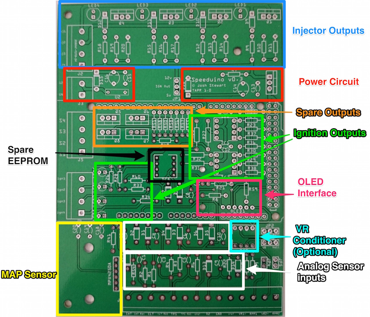
- 4 injector channels
- 4 Ignition outputs
- Fully protected input channels for CLT, IAT, TPS and O2
- Optional VR conditioner mount on crank and cam inputs
- MAP sensor mount location
- 4 medium current spare outputs (Eg Fuel pump, thermo fan etc)
- All I/O through screw terminals on the board
- Optional EEPROM mount (Not currently in use, but expected for future potential support of Arduino Due)
- OLED breakout header
Physical Layout
Board Assembly
Assembly of a complete board is relatively straightforward with all components being through hole and labelled on the board. Whilst it does not matter which order components are installed, the following is recommended for simplicity:
-
All resistors
-
All diodes (Including LEDS)
-
All capacitors
- Take note that C14 and C16 are polarised capacitors, meaning that they must be put in the correct way around. The capacitors should be marked with a + sign on one side. On the PCB, the positive side is indicated by a line on the capacitor symbol.
-
All jumper headers (JP*)
-
Arduino pins:
- Suggested method: Break header pins into required lengths and insert into an Arduino Mega. Place the board over the top of the pins and solder in place
- Note that not all the pins on the end double row need to be populated (Though there's no harm in doing so). The odd numbered pins (Eg D23, D25 .. DD53) do not need pins on them.
-
IC sockets
-
MAP sensor (If used)
-
All screw terminals
-
All MOSFETs
-
Power regulator
Board Configuration
The board can be configured in multiple ways depending on the hardware you use and way your setup is configured.
Optional Components
If using a VR crank sensor, the board will require the addition of a VR conditioner. The board has been designed to work with the dual VR conditioner from JBPerf (http://www.jbperf.com/dual_VR/index.html) which will plug directly in. Other VR conditioners will also likely work, but have not been tested.
Jumper Configs
Depending on the type of crank and cam sensors you have, there are a number of jumpers that will need to be set. The jumpers that need setting are:
- JP1 - This sets whether the Ignition outputs are 12v or 5v. Note that even if you set this to 12v you should **NOT** connect these directly to a high current coil. These outputs should only ever go to a logic level coil or an igniter
- JP2 - Whether or not the RPM1 (Crank) input should be routed via the (Optional) VR conditioner. This should be set to VR when using either a VR sensor or a hall sensor that switches between 0v-12v
- JP3 - Same as JP2, but for the RPM2 (Cam) input
- JP4 - 10k pullup resistor for RPM1 input. Should be jumpered ('On') when a sensor is used that switches between ground and floating (Which is most hall effect sensors)
- JP5 - Same as JP4, but for the RPM2 (Cam) input
To make this simpler, the most common sensor types and their required configurations are below:
| Crank Sensor | Cam Sensor | JP2 | JP3 | JP4 | JP5 |
|---|---|---|---|---|---|
| Floating Hall sensor | |||||
| (Ground and floating) | - | Hall | Off | On | Off |
| VR Sensor | - | VR | Off | Off | Off |
| 0v-12v Hall Sensor | |||||
| (Requires VR Conditioner) | - | VR | Off | Off | Off |
| Floating Hall sensor | |||||
| (Ground and floating) | Floating Hall sensor | ||||
| (Ground and floating) | Hall | Hall | On | On | |
| VR Sensor | Floating Hall sensor | ||||
| (Ground and floating) | VR | Hall | Off | On |