14 KiB
Overview
The v0.4 board is a testing board that was developed with the goals of reproducing the existing v0.3 boards capabilities, but with the following improvements:
- Lower cost (Primarily due to reduced size, but also some component changes)
- More compatible with off the shelf cases/enclosures
- Stepper-style IAC driver option
- Has a single 40 pin connector for all IO (Excluding 12v power)
Note that the v0.4 is NOT intended as a replacement for the v0.3 line of boards! The 2 are designed with different goals in mind. The v0.4 is intended to be integrated more closely into existing wiring, with the aim being that interface boards can be used to easily connect through the IDC40 connector. Unless you understand the interface on the v0.4 board and believe it is the best option for your install, the v0.3 may well be a better option for you.
Board Features
The v0.4 boards includes the following features:
- 4 injector channels
- 4 Ignition outputs
- Fully protected input channels for CLT, IAT, TPS and O2
- Optional VR conditioner mount on crank and cam inputs
- MAP sensor mount location
- DRV8825 stepper module mount location
- 4 medium-current spare outputs (e.g., fuel pump, thermo fan, boost control, VVT, etc)
- 5 unpopulated/configured optional low-current spare outputs in "proto" section, including tachometer-out
- A single 40-pin IDC connector includes all pins required for the board with the exception of the 12v input
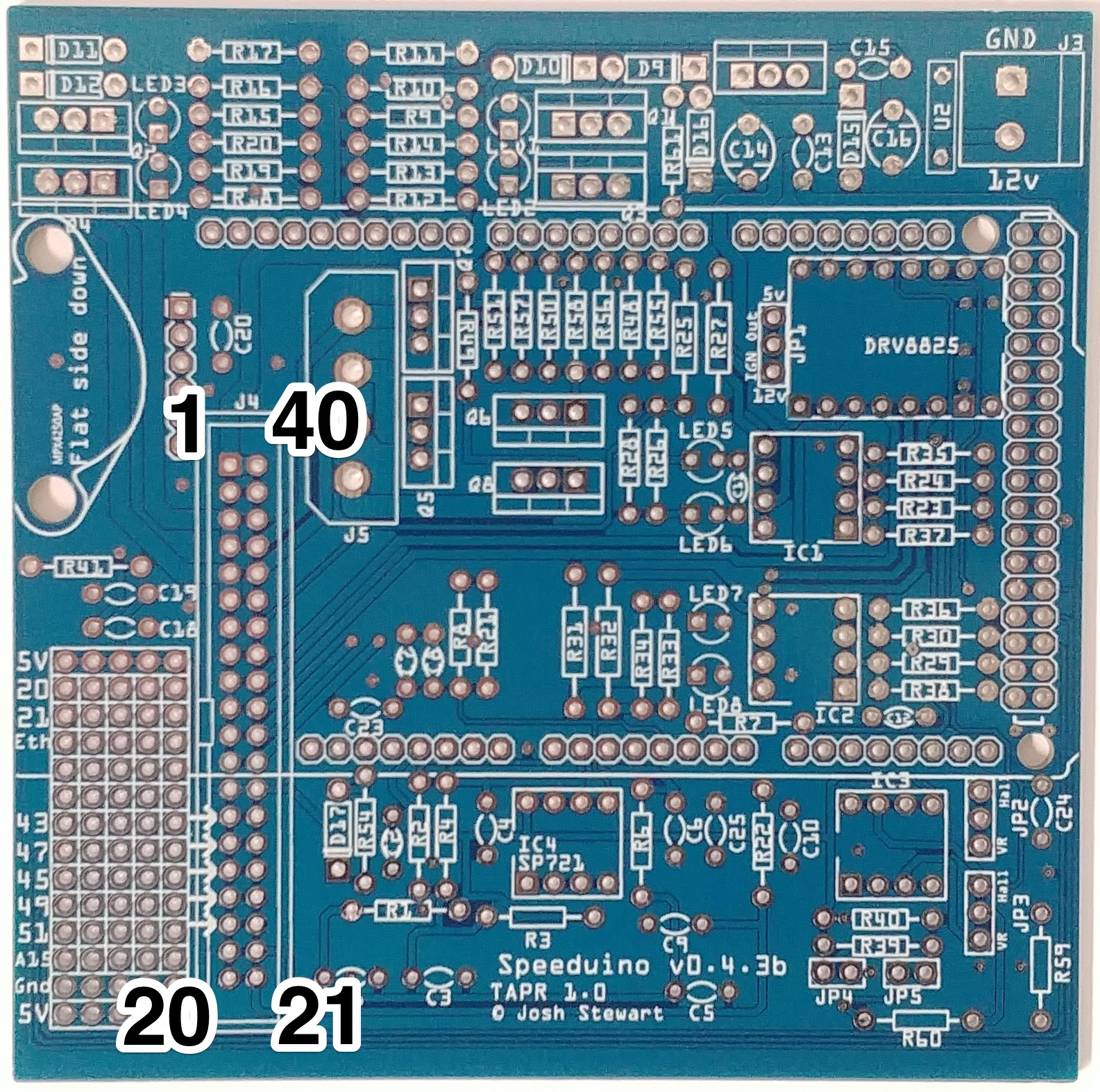
Physical Layout
Note that there are some differences between the various versions of the board, however the pinouts on the main IDC40 connector remain the same.
| Board Pins |
|---|
 |
Board Assembly
Assembly of a complete board is virtually identical to the v0.3 and remains relatively straightforward with all components being through hole and labelled on the board. Whilst it does not technically matter which order components are installed, the following is recommended for simplicity:
- All resistors
- All diodes (Including LEDS)
- All capacitors
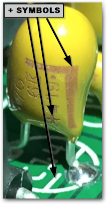
- Take note that C14 and C16 are polarised capacitors, meaning that they must be put in the correct way around. The capacitors should be marked with a + sign on one side. On the PCB, the positive side is indicated by a line on the capacitor symbol.
 1. All jumper headers (JP\*)
2. Arduino pins:
1. Suggested method: Break header pins into required lengths and insert into an Arduino Mega. Place the board over the top of the pins and solder in place
2. Note that not all the pins on the end double row need to be populated (Though there's no harm in doing so). The odd numbered pins (Eg D23, D25 .. DD53) do not need pins on them.
1. All jumper headers (JP\*)
2. Arduino pins:
1. Suggested method: Break header pins into required lengths and insert into an Arduino Mega. Place the board over the top of the pins and solder in place
2. Note that not all the pins on the end double row need to be populated (Though there's no harm in doing so). The odd numbered pins (Eg D23, D25 .. DD53) do not need pins on them.
- IDC 40 connector
- IC sockets
- All screw terminals
- All MOSFETs
- Power regulator
- MAP sensor (If used)
- NOTE: ALL self assembly boards have the MAP sensor with the hole at the top.
Assembly Instruction video
This video is for the v0.3 board, but it largely applies to v0.4 designs as well.
IjKlmIi_Dug Board Configuration -------------------The board can be configured in multiple ways depending on the hardware you use and way your setup is configured.
Board default outputs
Multiple functions within Speeduino have adjustable outputs or can be set to Board Default. The following are the Default pin outs for the v0.4, however all of these functions can be reassigned to other pins if required (Eg to use the onboard high current outputs)
| Function | Board output | Arduino pin |
|---|---|---|
| Boost control | IDC Pin 35 | 7 |
| VVT | IDC Pin 38 | 4 |
| Idle 1 | IDC Pin 37 | 5 |
| Idle 2 (3 wire idle valves) | IDC Pin 36 | 6 |
| Fuel pump | Proto area (45) | 45 |
| Fan | Proto area (47) | 47 |
| Tacho | Proto area (49) | 49 |
| Launch / Clutch | Proto area (51) | 51 |
Optional Components
If using a VR crank sensor, the board will require the addition of a VR conditioner. The board has been designed to work with the dual VR conditioner from JBPerf (http://www.jbperf.com/dual_VR/index.html) which will plug directly in. Other VR conditioners will also likely work, but have not been tested. There is now also an official VR board that can be used, see link on the left.
SP721 Over-voltage Protection
For users having difficulty obtaining the SP721 used in some versions, see info on the SP721 Diode Alternate page.
Jumper Configs
Depending on the type of crank and cam sensors you have, there are a number of jumpers that will need to be set. The jumpers that need setting are:
- JP1 - This sets whether the Ignition outputs are 12v or 5v. Note that even if you set this to 12v you should **NOT** connect these directly to a high current coil. These outputs should only ever go to a logic level coil or an igniter
- JP2 - Whether or not the RPM1 (Crank) input should be routed via the (Optional) VR conditioner. This should be set to VR when using either a VR sensor or a hall sensor that switches between 0v-12v
- JP3 - Same as JP2, but for the RPM2 (Cam) input
- JP4 - 1k pullup resistor for RPM1 input. Should be jumpered ('On') when a sensor is used that switches between ground and floating (Which is most hall effect sensors)
- JP5 - Same as JP4, but for the RPM2 (Cam) input
To make this simpler, the most common sensor types and their required configurations are below:
| Crank Sensor | Cam Sensor | JP2 | JP3 | JP4 | JP5 |
|---|---|---|---|---|---|
| Floating Hall sensor | |||||
| (Ground and floating) | - | Hall | Off | On | Off |
| VR Sensor | - | VR | Off | Off | Off |
| 0v-12v Hall Sensor | |||||
| (Requires VR Conditioner) | - | VR | Off | Off | Off |
| Floating Hall sensor | |||||
| (Ground and floating) | Floating Hall sensor | ||||
| (Ground and floating) | Hall | Hall | On | On | |
| VR Sensor | Floating Hall sensor | ||||
| (Ground and floating) | VR | Hall | Off | On |
40-pin connection
You can solder wires directly to the board or use IDC (Insulation Displacement Contact) connectors. The 40-pin IDC is the connector that was used on computer drive ribbon cables for years and old computer cables can be used. A heavier cable, called DuPont cable is recommend for long term use though. Later in the IDE/ATA interfaces life the speed was increased and this required a new fine 80-wire cable. These cables are NOT compatible. Some of the pins are connected together causing the magic blue smoke to be released.
Board revisions
| Version | Changes | BOM |
|---|---|---|
| V0.4.4b | A new ground up, all SMD, board design that includes additional onboard drivers and protection circuits. It is electrically and physically compatible with all other v0.4 versions. | Not Required |
| V0.4.4 | Modified for easier automated assembly, including some SMD components and mounting the pressure sensor flat side up. Run/program switch added. Only sold officially as complete boards | Not Required |
| V0.4.3 | Filter capacitors added to both primary and secondary RPM inputs. Voltage clamp added to secondary RPM input. Flex fuel input added to proto area | Download |
| V0.4.2 | Considerable number of routing improvements. Neater proto area layout. Voltage clamp added to primary RPM input | Download |
| V0.4.1 | Added Proto area. Replaced diode array with SP721. Added optional high current aux output socket (J5). Diode relocated on power circuit to prevent USB back feeding 5v onto 12v rail when ignition off | Same as v0.4.2 |
| V0.4 | Initial release | Download |