3.2 KiB
| title | description | published | date | tags | editor | dateCreated |
|---|---|---|---|---|---|---|
| VR_conditioner | true | 2021-07-16T08:02:16.412Z | undefined | 2020-01-06T01:53:46.712Z |
Overview
For its crank and cam signals, Speeduino requires 3.3v-5v square wave pulses. Such signals can be inputted directly from hall or optical sensors, however the common Variable Reluctance (VR) sensor requires conditioning in order to convert its AC signal. Speeduino has an onboard socket and jumper system to allow for simple use of a plug in conditioner board.
VR conditioners need to have Trigger Edge in TunerStudio set to the correct option based on the conditioner you are using. Rising for MAX or LM conditioners, and Falling for most others.
Conditioner Board
The plug in dual VR conditioner board has been developed and is for sale as well as having its design files make available on github (https://github.com/speeduino/Hardware/tree/main/VR%20Conditioner/Latest). The board can take either a single VR signal input or one for both the cam and crank.
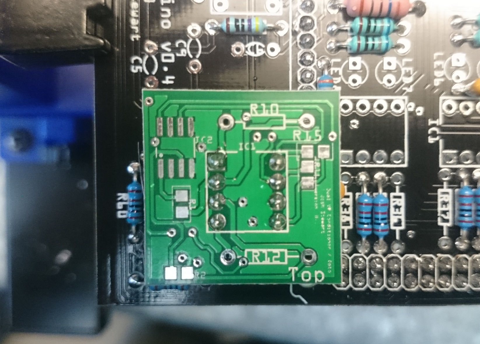
Note: The same PCB is used for both the VR conditioner and as a dual Opto isolator. It is populated on 1 side only, depending on which configuration is needed. For VR conditioning, only the bottom side of the board is populated, so don't be alarmed that the side labelled Top is left bare.
This board is physically and electrically compatible with other boards such as those from JBPerf. The Speeduino version is offered as an open hardware alternative to these.
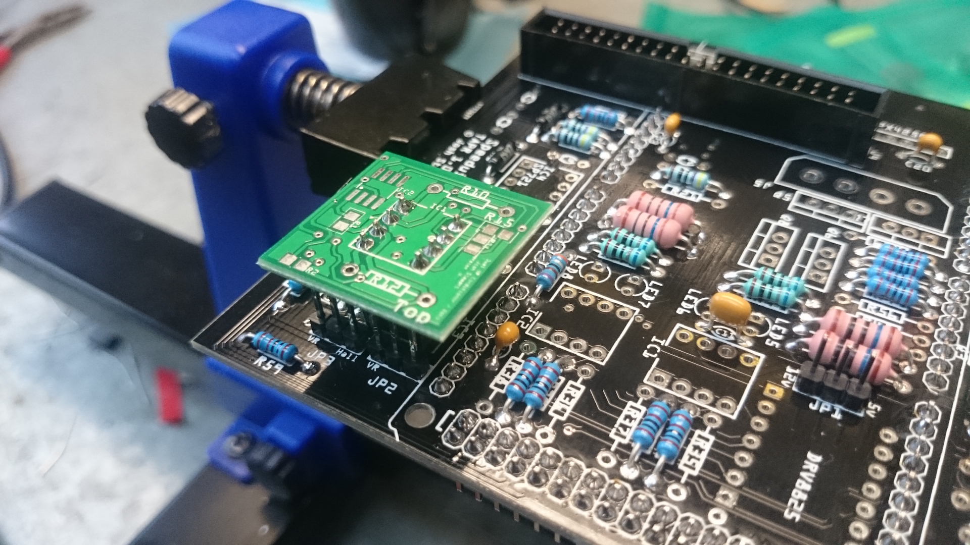
Mounting
The board can be mounted onto Speeduino fairly simply. To provide maximum clearance, it is recommended that the socket on the Speeduino is populated with female headers to lift the VR board away from other components. The following images show the mounting orientation of the VR board.
Jumper configuration
It is critical that the jumpers on the Speeduino board be set appropriately to use the VR conditioner. Failure to do so could cause damage to your Arduino if the high voltage signal from the VR sensors is passed through directly due to incorrect jumper settings.
See the jumper settings table on the page for your board for how these should be configured for 1 or 2 VR inputs.
Technical
The board is based around the reference design for the MAX9926 adaptive conditioner from Maxim. It optionally has mounting holes for 2 shunt resistors (R10 and R12) that can be installed to alleviate noise issues at high RPMs should it be a problem. If needed, these resistors should be of value 10k and rated for at least 1W.
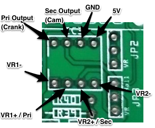
Alternative uses
Whilst the 'VR' socket on the Speeduino board was initially designed for a VR conditioner, it can be used to process any incoming signal. An example of this would be an opto isolator to bring a 0-12v signal down to a safe 0-5v range. For reference, the pinout of the socket is shown below: