18 KiB
| title | description | published | date | tags | editor | dateCreated |
|---|---|---|---|---|---|---|
| Idle | true | 2023-07-14T02:58:03.029Z | markdown | 2020-01-06T01:53:59.753Z |
Idle Control
Overview
The idle control outputs are used to alter the state of an idle control valve to increase the amount of air entering the engine at idle. These come in multiple types (Described below) and each is configured and tuned differently.
Open and closed loop idle control is available for both PWM and Stepper based idle valves.
Compatible Idle Valve Types
There are currently 3 modes of idle control available, using on/off, PWM duty cycle, or a stepper step count, enabled below a set coolant temperature. These modes cover the most common types of idle mechanisms in use.
On/Off (aka Fast Idle)
This is a simple digital on/off "switch" output by Speeduino that triggers at a selected temperature. It is intended to control an on/off fast idle valve as found in many older OEM setups, or an open/closed solenoid-type valve that is chosen for the purpose. In addition to OEM idle valves, examples of valves popular for re-purposing as on/off idle valves are larger vacuum, breather, or purge valves, and even fuel valves. Idle speed adjustment is generally set only once, with an in-line adjustable or fixed restrictor, pinch clamp, or other simple flow-control method.


Note: On/Off valves can be used in many ways to increase or decrease air flow for various idle purposes in-addition to warm-up. Examples are use as dashpot valves to reduce deceleration stalling, idle speed recovery for maintaining engine speed with accessory loads such as air conditioning, or air addition for specific purposes such as turbo anti-lag air control. See Generic Outputs for control information.
PWM
While similar in construction to many solenoid on/off valves; PWM idle valves are designed to vary the opening, and therefore flow through the valve, by PWM valve positioning.
These valves are opened and closed by varying the duty cycle of signal sent to them.
Note: As a fail-safe, some PWM idle valves default to a partially-open state when they are disconnected or are receiving 0% duty cycle. They will close then re-open with increasing PWM DC%, so be sure to research or test your valve type for proper operation. {.is-info}
PWM Settings
Settings in TunerStudio include selecting PWM idle control, temperature and DC settings for warmup, and PWM DC during cranking under the following selections:
 {.align-center width=350}
The 'Idle - PWM Duty Cycle' and 'Idle - PWM Cranking Duty Cycle' options will only be available when 'PWM Open Loop' is selected in the Idle Control options
Under Idle control type, PWM is selected:
 {.align-center width=400}
The temperature-versus-DC is selected under the Idle - PWM Duty Cycle selection. Note the relationship between temperature and PWM DC can be altered by simply moving the blue dots in the curve, or by selecting the table for manual entry as shown here:
 {.align-center width=400}
Some engines prefer additional airflow during cranking for a reliable start. This air can be automatically added only during cranking by using the Idle - PWM Cranking Duty Cycle settings. Once the engine starts and rpm rise above the set maximum cranking rpm, the idle control switches to the previous warmup settings. Note the relationship between coolant temperature during cranking and PWM DC can be altered by simply moving the blue dots in the curve, or by selecting the table for manual entry as shown here:
 {.align-center width=400}
NOTE: Every engine, valve type and tune is different. Suitable settings must be determined by the tuner. Do not infer any tuning settings from the images in this wiki. They are only examples. {.is-warning}
2 wire vs 3 wire valves
Both 2 and 3 wire PWM idle controllers are supported. In general, the 3 wire models will provide a smoother response than the 2 wire ones, but the difference is not always significant. For 3 wire valves, 2 of the Aux outputs will be required.

Stepper Motors
Stepper motor idle controls are very common on GM and other OEM setups. These motors typically have 4 wires (bi-polar). They must be driven through power transistors or a driver module, such as the DRV8825 stepper motor driver optional to the v0.4 board. These driver modules can be purchased inexpensively from a variety of vendors on sites such as eBay, Amazon, etc.
Most stepper idle valves function by turning a threaded rod in and out of the valve body in a series of partial-turn steps, increasing or decreasing airflow around the plunger (on end of valve below), and into the engine. The idle airflow bypasses the primary throttle body:

Example of a generic DRV8825 driver module on a v0.4 board:

Note the board is mounted at a standoff for air circulation and cooling:

The DRV8825 motor outputs are labeled as A2-A1-B1-B2, and the wiring connection examples are to this labeling. Check your schematics for the output connections that route to these DRV8825 outputs:
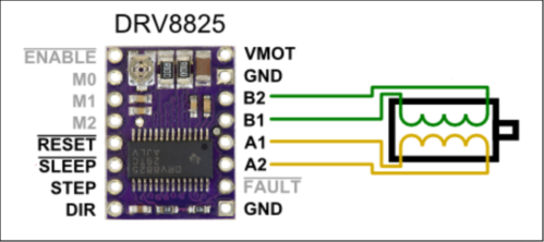
Examples of wiring to the DRV8825 driver:
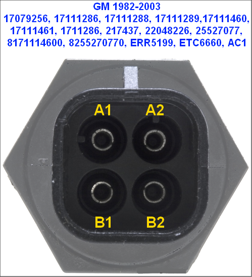
The GM "screw-in" style used 1982 to 2003 on many models:
Stepper Driver Current Adjustment
The DRV8825 stepper driver module includes a potentiometer (adjustable resistor) indicated by the yellow arrow in the image below. The potentiometer is used for setting the driver's maximum current output limit. Because Speeduino uses full-step operation, the current limit is not critical to protect the module, but should be adjusted to the module's maximum value for best operation of most automotive stepper IACs.

You will need a multi-meter or volt-meter to make the adjustment as outlined here. In order to set the potentiometer to maximum current before first use, ensure power to the module is OFF, then gently turn the potentiometer dial clockwise to the internal limit. Do not force the adjustment beyond the internal stop. Power-up Speeduino with 12V, and use the meter to test the voltage between the center of the potentiometer and any 12V ground point. Note the voltage reading. Power-down and repeat the test, this time turning the potentiometer counter/anti-clockwise gently to the internal limit. The test direction that resulted in higher voltage is the correct setting for the module.
Note: Original Pololu modules are typically adjusted clockwise for maximum voltage. However, clone modules may be either clockwise or counter-clockwise, which makes this testing necessary.
The module's rated continuous current is up to 1.5A. While the module can supply a peak of 2.2A of current; in full-step mode and with the potentiometer adjusted to this position, the driver is limited to approximately 70% of full current, or approximately 1.5A.
Stepper Settings
Settings in TunerStudio include selecting stepper idle control, temperature and step settings for warmup, and open steps during cranking under the following selections:

Under Idle control type, stepper is selected. The basic stepper operational settings are also located in this window:
 {.align-center width=350}
- Step time: This is how long (in ms) that the motor requires to complete each step. If this is set too low, the idle motor will not have completed the step before the ECU tries to make the next one, which leads to the motor 'twitching' and not functioning correctly. If this is set longer than needed the system will take longer to make each adjustment and the overall idle response will be slower. Typical values are usually 2ms - 4ms. The common GM stepper motor requires 3ms.
- Cool time: Some motors require a slight pause in between steps in order to function correctly. This is know as the 'cooling' time. Typically this value will be less than 4ms at the most, with many motors operating normally with no cooling period (0ms)
- Home Steps: Stepper motors must be 'homed' before they can be used so the that ECU knows their current position. You should set this to the maximum number of steps that the motor can move.
- Minimum steps: In order to allow a smooth idle that isn't continually fluctuating, the ECU will only move the motor if at least this many steps are required. Typical values are in the 2-6 range, however if you have a noisy coolant signal line, this value may need to be increased.
- Don't exceed: In order to prevent the stepper motor attempting to move beyond it's maximum range, this is a limit placed on the total number of steps that will be made. The value in this field must always be lower than the number of homing steps
- **Stepper Inverted: ** Polarity of stepper pulses will be inverted
- **Stepper Power: ** Whether the stepper motor is only powered when performing a step or constantly. Most stepper motors only require power when stepping/active and can overheat it powered constantly, however for 'free wheel' valves that will close when unpowered, select Always
The temperature-versus-steps is selected under the Idle - Stepper Motor selection. Note the relationship between temperature and motor steps can be altered by simply moving the blue dots in the curve, or by selecting the table for manual entry as shown here:
 {.align-center width=400}
Some engines prefer additional airflow during cranking for a reliable start. This air can be automatically added only during cranking by using the Idle - Stepper Motor Cranking settings. Once the engine starts and rpm rise above the set maximum idle rpm, the idle control switches to the previous warmup settings. Note the relationship between coolant temperature during cranking and motor steps can be altered by simply moving the blue dots in the curve, or by selecting the table for manual entry as shown here:
 {.align-center width=400}
NOTE: Every engine, valve type and tune is different. Suitable settings must be determined by the tuner. Do not infer any tuning settings from the images in this wiki. They are only random examples. {.is-info}
NOTE: Refer to the Pololu video for instructions to set the DRV8825 driver current level to maximum for most automotive full-step stepper motors.
Examples
| Motor | Step time | Home steps |
|---|---|---|
| GM 4-wire | 3 | 250 |
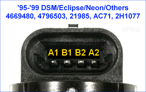
| DSM 4-wire | 4 | 270-320 |
NOTE: While normal DSM stepper function is seen at room temperatures at 3ms, step skipping occurs just under that speed. Very cold temperatures may cause skipping, thus the recommendation of 4ms. Test for the most suitable speeds for your setup.
Stand-Alone (Non-Electronic)
While not an idle control mode, Speeduino is compatible with stand-alone idle valves that are self-controlling. Examples of this are thermal wax or bi-metal spring idle or auxiliary air valves like the one below. Internally expanding and contracting material opens and closes air valves, providing increased air flow and engine rpm when cold for warmup. Speeduino functions to enrich the cold engine and adjust for the additional air, in the same way it would if you opened the throttle slightly.

Other examples of stand-alone valves are simple On/Off valves as shown in the next section, controlled by inexpensive thermal switches like these:


Closed Loop Control
Closed loop idle control operates by setting RPM targets and configuring the duty cycle or steps directly. A PID algorithm is used and can be tuned to match the valve/motor that you are using. Pure open-loop is only still in the firmware because of backwards compatibility with existing tunes/installs. It does not disable with throttle command from the driver or when engine braking.
For new installs open+closed loop is recommended.
Open+Closed Loop Control
The open+closed loop idle controller is used to keep a accurate idle RPM, even when influenced by various disturbances.
The concept of open+closed loop idle control is that it uses the open-loop PWM values and on top of that closed-loop PID control to handle any disturbances like power-steering, air-co, electrical loads, temperature variation etc. The idle is already in the ballpark using the open-loop steps/duty-cycle lookup curve. And the PID controller is keeping it on target RPM.
Idle control Open+Closed loop settings
In the idle control menu first select the "PWM Open+Closed loop" or the "Stepper Open+Closed loop" function to active one or the other. Depending on the idle control valve fitted to the car. Setup your idle valve according to what valve you have it should be the same as the open-loop settings.
In the "Closed loop idle" part you can setup the PID feedback controller gains. P,I,D.
Example idle settings window.
 {.align-center width=400}
PID Gains
The gains are used to tune the PID controller. Look on the web for various manuals to tune PID controllers. The Idle PID controller uses a setpoint (idle Target RPM) and a Measurement (Crank position sensor) to calculate an output over time to keep the engine RPM as close as possible to the Target RPM. How aggressive the controller tries to keep this target is determined by the PID gains.
A PID controller calculates the following formula every step. (controller action = (Kp * error) + (Ki * accumulated error) - (Kd * (error - previous error)) )
Some hints while tuning.
- P gain reacts directly on the error
- I gain reacts over time on a error, it slowly fills a buffer of errors to counteract any steady-state error left over by the P gain
- D gain reacts on the rate of change (speed) of the error. It dampens the too quick of a reaction of the controller. For example when it quickly moves toward the target set-point and tends to overshoot its target.
Valve minimum/maximum duty cycle
The minimum and maximum duty cycle set how much of the 0% to 100% duty cycle is available for the open-loop + closed-loop feedback control. The PWM output is limited to those values. Make sure that the values are as wide a possible so the PID controller has some room to control the idle. If these values are to strict the controller can not keep the target RPM. These values are only fail-safe values and should never be reached with a properly tuned idle control system.
Integral reset TPS
There are two integral reset values. These are used to reset the accumulated error part of the PID controller when activated. Essentially this disables most of the PID controller action when one or the other function is active. The first one is based on the TPS. Usually this is set around 1% to 2%. If the TPS reads above this value the driver is using the throttle. To prevent the idle controller to counteract this throttle opening the accumulated error for the I gain will be reset to 0 continuously.
Integral reset RPM hysteresis.
The second one is based on RPM. If the car is in gear rolling to a traffic light with no pedal input the controller must also not try and compensate this higher RPM by closing the idle valve, even when the TPS reads 0%. The accumulated error will keep filling up. So the RPM value represents when the controller must start trying to keep idle target RPM again. The threshold is calculated as "RPM hysteresis" + "idle RPM target". When below this value the closed loop controller starts and tries to keep it on target again.
- Example: Target RPM from the target curve is 750 RPM. RPM hysteresis value is set at 500 RPM. The controller starts trying to keep it at its target RPM again if the egine RPM is below 1250 RPM.
IAC PWM duty curve
The IAC PWM curve is used to lookup what PWM duty cycle will be output to the idle control valve for a certain engine temperature. This is just like the open-loop idle function. Tune this curve first before starting open+closed loop tuning. Tune it so that the actual RPM is a bit above the desired RPM target value to prevent the engine stalling after engine braking. Tune this table while idle control is set to open-loop, or set all PID gains to 0 and tune it.
Example IAC duty curve
 {.align-center width=400}
Idle RPM targets curve
The RPM target curve is used to lookup what the idle RPM target will be for the a given engine temperature. This will be used in the PID feedback controller to keep idle RPM at this target.
Example Idle RPM targets curve
 {.align-center width=300}