|
|
||
|---|---|---|
| .github | ||
| case_blank_plug_3d | ||
| gerbers | ||
| git_scripts | ||
| hellen-one@7114c97fe5 | ||
| images | ||
| rusefi_lib | ||
| rusefi_lib_external@eb70637ed6 | ||
| test_fixture | ||
| .gitignore | ||
| .gitmodules | ||
| CKKB48-1-A.pdf | ||
| CKKB48-1-A_both_sides.jpg | ||
| FlashMemory.kicad_sch | ||
| TLE8888-1QK.kicad_sch | ||
| TLE9201SG.kicad_sch | ||
| adc.kicad_sch | ||
| case_model_3d.x_t | ||
| compatible_ST-LINK_V2.jpg | ||
| fp-lib-table | ||
| hi-lo.kicad_sch | ||
| inputs.sch | ||
| microRusEfi.jpg | ||
| microRusEfi_Schematic_0_3.pdf | ||
| microRusEfi_Schematic_0_4_5.pdf | ||
| microRusEfi_Schematic_0_4_7.pdf | ||
| microRusEfi_Schematic_0_4_8.pdf | ||
| micro_rusEFI-cache.lib | ||
| micro_rusEFI.kicad_pcb | ||
| micro_rusEFI.kicad_prl | ||
| micro_rusEFI.kicad_pro | ||
| micro_rusEFI.kicad_sch | ||
| micro_rusEFI.xml | ||
| micro_rusEFI_PCB.pdf | ||
| micro_rusEFI_Schematic_0_5_0.pdf | ||
| micro_rusEFI_Schematic_R0.5.1.pdf | ||
| micro_rusEFI_Schematic_R0.5.2.pdf | ||
| micro_rusEFI_back.jpg | ||
| micro_rusEFI_by-ref.csv | ||
| pair.kicad_sch | ||
| readme.md | ||
| releaseNotes.md | ||
| stm32.kicad_sch | ||
| sym-lib-table | ||
| version.txt | ||
| zMRETestFixture.kicad_pcb | ||
| zMRETestFixture.pro | ||
| zMRETestFixture.sch | ||
| zMRETestFixture_PCB_layout.pdf | ||
| zMRETestFixture_Schematic.pdf | ||
readme.md
microRusEFI
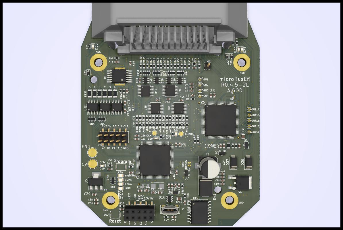
microRusEFI is a small & cheap engine management system board designed for fully sequential 1, 2, 3 and 4 cylinder applications.
6 and 8 cylinders are possible with some limitations. 5 cylinder application not recommended. You would need at least two microRusEFI units to run a v12.
microRusEFI uses a waterproof connector and its aluminum enclosure could be sealed.
microRusEFI hardware runs rusEFI firmware.
microRusEfi supports dual Hall shaft position sensor input or 1xHall + 1xVR shaft position sensor input (A few resistors must be replaced on the PCB in order to switch from one setup to another)
Open source design available in this repository, or available as a kit or completely assembled from https://www.ebay.com/itm/333532119947
Capabilities
- Primary VR or Hall input (configurable with few resistor changes)
- Secondary Hall input
- x4 analog thermistor (temperature) inputs
- x10 analog voltage inputs (0-5v)
- x4 high-Z injector outputs
- x2 high-current low side outputs for IAC/VVT/other solenoids
- Dedicated main relay control output
- x4 low-current low side outputs for relays or warning lights
- x4 5v logic-level ignition outputs
- x2 5v/12v configurable logic level outputs (requires resistor changes)
- Electronic throttle body (drive by wire)
- CAN connectivity on the plug
- USB connectivity on the plug
- SPI and TTL available on PCB
- stepper IAC support (beta testing please report your results!)
Documentation
microRusEFI documentation wiki
asembled images & assembly files
If you download complete repo do not forget to download libraries. If you git clone be sure to also
git submodule update --init
Do you like what you see here? Maybe https://www.patreon.com/rusefi
BOM highlights
stm32f767
Adapter Boards
microRusEFI could be used as a brain for Plug&Play vehicle specific adapter boards
- https://github.com/rusefi/hw_55_te For Yanvar/Micas case
Case
Model CKKB48-1-A (Weigh 200g)
Cover bolts M3.5x0.6
PCB bolts M3 0.5mm thread, L=7.5mm https://www.mcmaster.com/94209A619/
Gerbers
Gerbers and pictures of fabricated boards
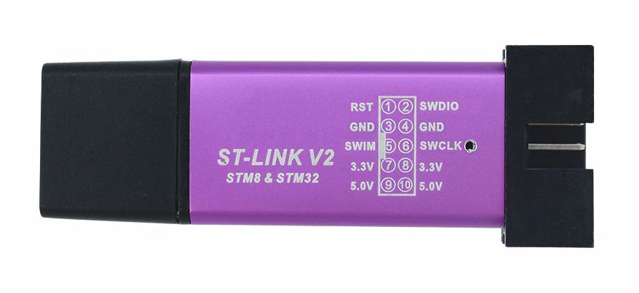
ST-LINK
Unfortunately eBay has a few different version of cheap ST-LINK V2 devices with different pinout. Here is the pinout rusEfi is compatible with:

